


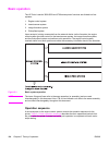

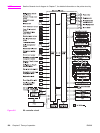
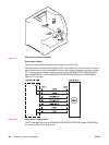
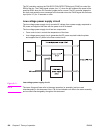

Block functions
CPU (IC1001)
The 16-bit single-chip microcomputer that constitutes the CPU incorporates ROM and RAM
and controls the following operations of the printer according to the control programs stored
in the ROM:
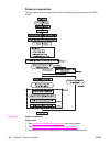
1. Printer engine sequence
2. Fuser heater drive circuit/fuser safety monitor circuit
3. Solenoids
4. Clutches
5. Sensors/switches
ASIC (IC1002)
The application specific IC (ASIC) is used to interface to the IC, the memory, the external
devices, and so on. It controls the following operations of the printer according to the
commands from the CPU:
1. Laser/scanner
2. Communication with the formatter
3. High-voltage power supply circuit
4. Each motor’s drive
5. Fan motor’s drive
6. Writing and reading data to and from the EEP-ROM
7. Memory tag
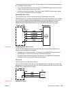
Reset IC (IC1003)
The IC1003 monitors +3.3V voltage and resets the CPU and ASIC when the power is turned
on.
EEP-ROM (IC1010)
EEP-ROM stores various backup data.
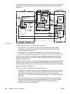
Feeder motor driver IC (IC1011)
IC1011 controls the feed motor. (See
Motors, solenoids, and clutches, below for details.)
Delivery motor driver IC (IC1014)
IC1014 controls the delivery motor and primary transfer engaging motor. (See
Motors,
solenoids, and clutches, below for details.)
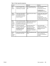
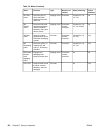
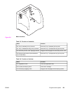
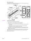
Motors, solenoids, and clutches
This printer has seven motors, four solenoids (three for the HP Color LaserJet 3500/3550
series printer), and three clutches for paper feed and image formation. The specifications of
such motors, solenoids, and clutches are listed in the following tables.
The motors with failure detector are discussed in
Failure detection.
ENWW Engine control system 121