


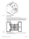
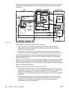

The major recipients of the +24 V, +5 V, and +3.3 V DC power are listed below.
● +24 V: motors, solenoids, clutches, high-voltage power supply PCB, memory controller
PCB, and optional parts
● +5 V: laser driver PCB, high-voltage power supply PCB, formatter, and sensors (except
for the photo interrupter)
● +3.3 V: formatter, sensor (photo interrupter), ICs inside the control panel, DC controller,
and the memory controller
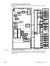
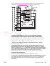
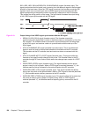
Protective function
The low-voltage power supply circuit has a protective function against overcurrent and
overvoltage to prevent failure in the power supply circuit. It automatically breaks the output
voltage when overcurrent or overvoltage occurs due to an issue, such as a short at the load
side.
CAUTION
Turn off the power switch (SW3001) to repair the load side, then turn the power back on
after the repair is complete, since the DC voltage from the low-voltage power supply circuit
may be stopped by this function.
There are two power supply fuses (FU3001, FU3002) in the circuit which have a protective
function. The power supply fuse opens and interrupts the current when an overcurrent
occurs in the AC line.
CAUTION
To recover the low-voltage power supply after it has been broken for protection, turn the
power off (by switching off or unplugging) and leave the printer off for three minutes or longer
before turning the power back on.
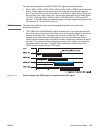
Safety
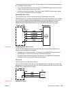
For the safety of users and service technicians, the +24 V is divided into two: +24 VA and
+24 VB. The +24 VA is supplied from the DC controller all the time, whereas the power
supply of the +24 VB stops when the door-open detection switch (SW1) is cut off. The high-
voltage power supply circuit, motors, and solenoids are supplied with the +24 VB. They stop
when the front cover is opened. This is to protect the users and the service technicians from
an electric shock or injury to their hands.
The +24 VB also functions as a DOOR-OPEN DETECTION signal (DOPEN). The CPU
judges the door open when the +24 VB supply stops.
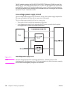
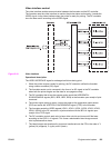
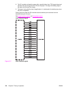
Sleep mode
This function saves the power consumption of the printer. It is controlled by the DC controller
and goes through the following sequence:
1. The DC controller receives a sleep command from the formatter.
2. The DC controller then sends the SLEEP signal (/REM24) to the low-voltage power
supply circuit within the specified time from receipt of such command. (“L” to “H”).
3. When /REM24 signal (“H”) is sent, the low-voltage power supply circuit stops the power
supply of 24V to each load and puts the fuser temperature control, fans, and motors into
the STOP state.
The printer returns to the WAIT period when it receives the command to release the sleep
mode from the formatter.
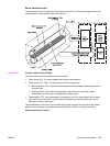
High-voltage power supply circuit
This circuit applies a bias to the primary charging roller, the developing cylinder, the
developing blade, the primary and secondary transfer charging rollers, and the pressure roller.
132 Chapter 5 Theory of operation ENWW