


2. The DC controller detects the density of the density detection patterns on the ITB by the
image density detection and sends the data back to the formatter. (See
Figure 5-56.
Image density detection, below)
3. The formatter calibrates the halftone based on such data to obtain an ideal halftone
image.
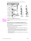
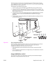
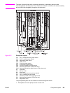
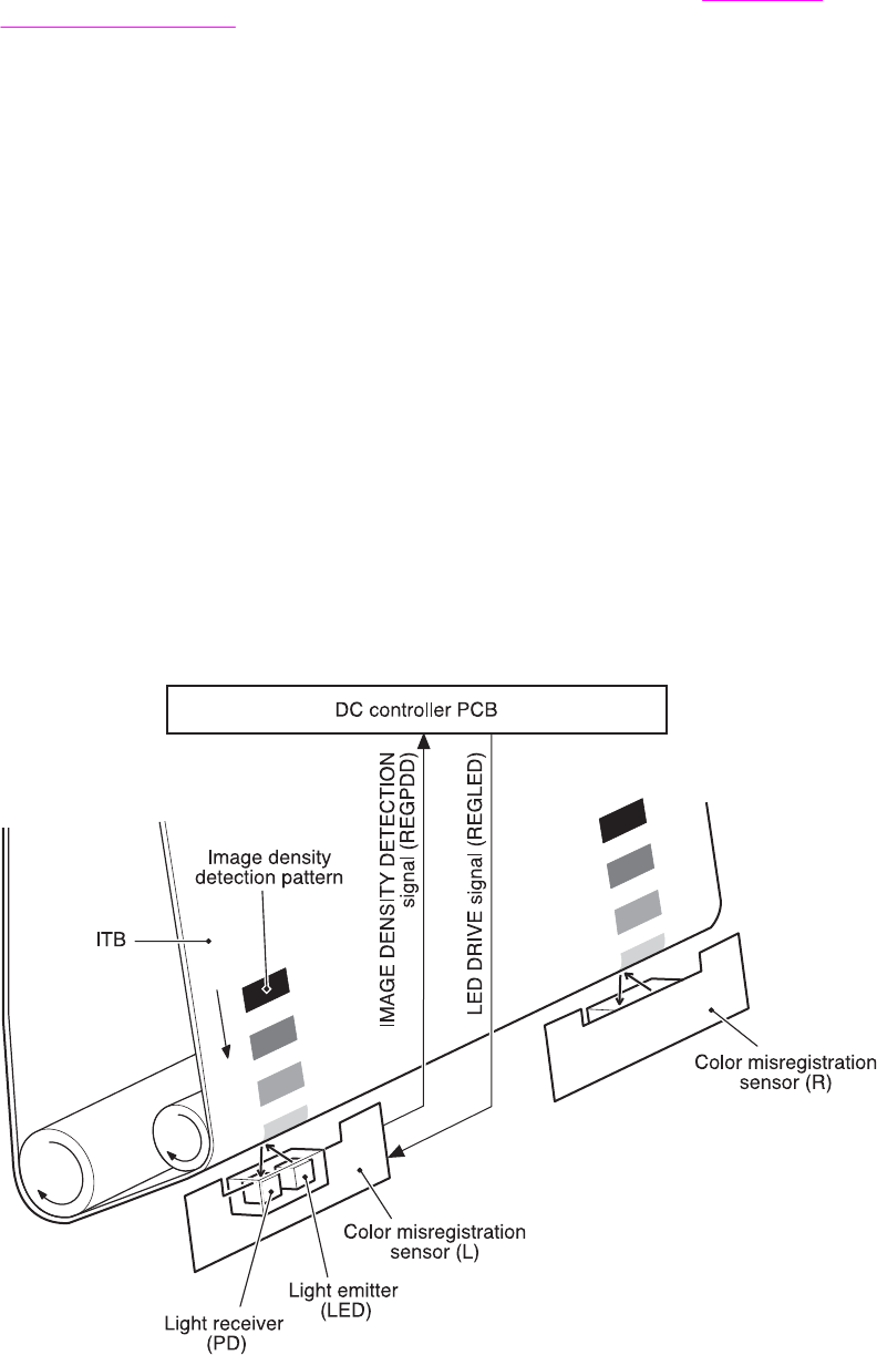
Image density detection
The density of all four colors’ image density detection patterns formed on the ITB is detected
to adjust the image density.
The DC controller controls the color misregistration sensor (PS5) during the foregoing D-max
and D-half controls for this detection. PS5 consists of two detection sensors, which are used
in conjunction with the images on the ITB, each having one light emitter (LED) and one light
receiver (PD).
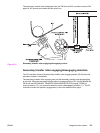
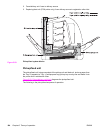
The following is the sequence of this control.
1. The DC controller sends LED DRIVE signal (REGLED) and lets the LED emit light.
2. The light of the LED is reflected off the density detection patterns on the ITB and
received by the PD on the sensor. The light amount received at the PD differs
depending on the toner density where the light is reflected off.
3. The light receiver converts the received light amount to voltage and sends it to the DC
controller in the form of the IMAGE DENSITY DETECTION signal (REGPDD).
4. The DC controller converts the REGPDD signals to density value (digital) and stores
them.
Figure 5-56.
Image density detection
180 Chapter 5 Theory of operation ENWW