


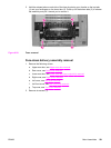
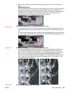
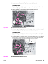
8. Remove two screws (3) and remove the swing rod/lock guide (4), shown in the above
figure.
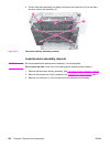
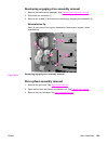
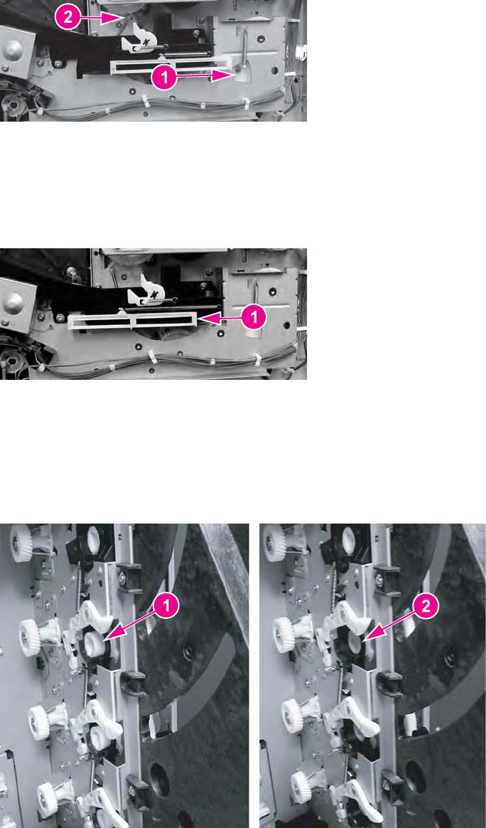
Reinstallation tip
When reassembling the swing rod guide, the engaging rack (callout (1) below) should be
positioned to the back (to the right) with respect to the printer, as shown below. The
engaging rack will normally be in this back position due to the tension of the spring. Also,
the gear behind the engaging rack should be turned all the way clockwise (2). To
reinstall the swing rod/lock guide, perform the following steps.
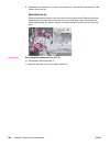
Figure 6-30.
Pick-up/feed engaging rack assembly replacement (1 of 2)
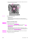
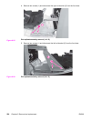
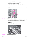
1. Insert the tab on the front of the swing rod/lock guide (callout (4), above) into the slot
in the printer frame (5), and then swing the back into position and install the two screws
(3).
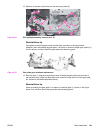
2. Once the swing rod/lock guide is installed, push the engaging rack all the way forward
(1), until it stops. This must be done to ensure that the print cartridge engaging pins are
in the disengaged position (as described below).
Figure 6-31.
Pick-up/feed engaging rack assembly replacement (2 of 2)
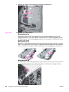
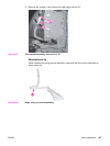
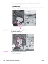
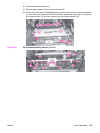
The above reassembly procedure ensures that, once the reassembly is complete, the
print cartridge engaging pins are pulled back or disengaged as shown by callout (2)
below. Callout (1) shows the pins extended or in the engaged position. If the engaging
pins are in the wrong position (if they are engaged) the front door will not close
because the print cartridge drive shaft will hang up on the engaging pins when the front
door is closed. This can result in damage to the engaging pins, print cartridges, or the
swing guide closing mechanism.
Figure 6-32.
Print cartridge engaging pins replacement
ENWW Main Assemblies 229