


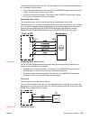
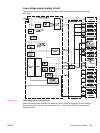
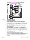
The DC controller controls the high-voltage power supply circuit and generates the high-
voltage bias. See
Image formation system for the details on image formation.
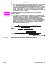
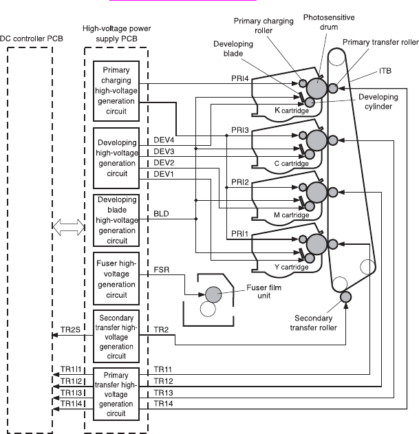
Figure 5-15.
High-voltage power supply circuit
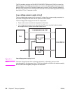
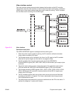
Primary charging bias generation
The primary charging biases (PR11, PR12, PR13, PR14) are used to charge the
photosensitive drum surface with negative potential to prepare for image formation.
They are the DC negative biases, PR14 for K (black) and the rest for colors (Y, M, C),
generated in the primary charging high-voltage generation circuit in the high-voltage power
supply circuit. The high-voltage power supply circuit applies these biases to the primary
charging rollers in each cartridge at the specified time.
The values of these biases vary according to the commands from the DC controller.
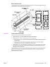
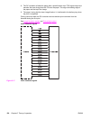
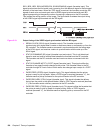
Developing bias generation
The developing biases (DEV1, DEV2, DEV3, DEV4) are used to adhere the toner to an
electrostatic latent image formed on the photosensitive drum. They are the DC negative
biases, one for each color (C, Y, M, K), generated in the developing high-voltage generation
circuit in the high-voltage power supply circuit. The high-voltage power supply circuit applies
these biases to the developing cylinders in each cartridge at the specified time.
The values of these biases vary according to the commands from the DC controller.
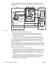
Developing blade bias generation
The developing blade bias (BLD) is output to charge the toner uniformly.
It is the DC bias. It is generated in the developing blade high-voltage generation circuit in the
high-voltage power supply circuit and shared by all colors (C, Y, M, K). The high-voltage
power supply circuit applies this bias to the developing blades in the cartridges at the
specified time.
ENWW Engine control system 133