


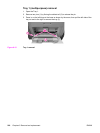
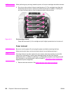
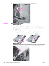
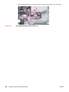
4. Remove five screws (3) and remove the image drive assembly (4).
Figure 6-23.
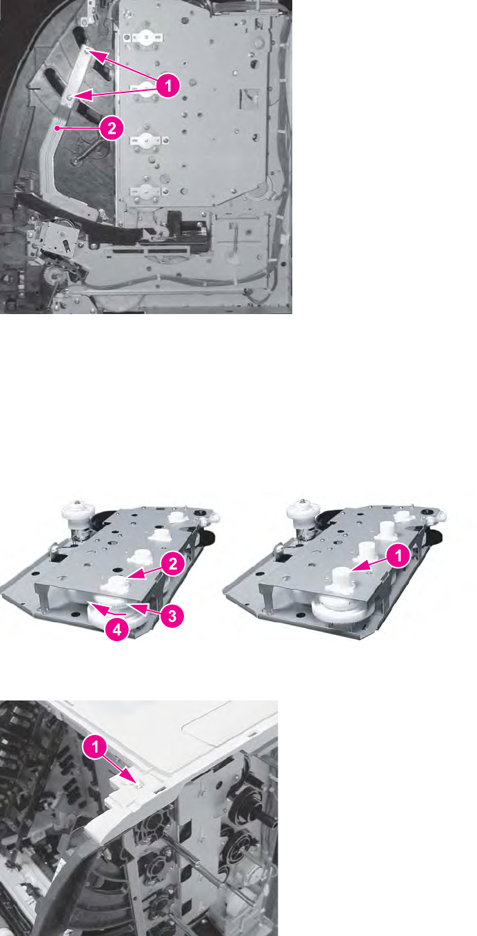
Image drive assembly removal
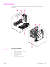
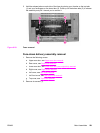
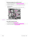
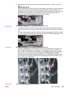
Reinstallation tip
When replacing the image drive assembly ensure that the engaging pins are in the
"engaged" position (1), as shown below. They should not be in the disengaged position
(2). If the pins are not in the disengaged position, turn the gear (3) in the direction of the
arrow (4) until it stops.
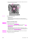
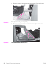
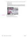
Reinstallation tip
Remember, replacement procedures are removal procedure steps performed in reverse
order. It is important that step 2, above, be performed after this step (step 4) to maintain
correct orientation of the gears and pins with respect to the engaging rack mechanism.
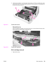
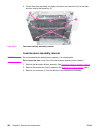
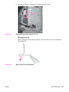
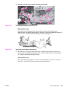
Reinstallation tip
For reassembly, remove the right front top cover screw (1). If this screw is not removed it
can prevent the upper left corner of the image drive assembly from seating correctly.
224 Chapter 6 Removal and replacement ENWW