8-14 SmartSwitch 1800 4.0 User Guide, Rev 01
1
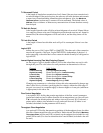
Once this parameter has been selected for the first time,
1
becomes the default value.
2
1–7
i f mo du lo 8,
1– 12 7
if modulo 128. Changing this parameter will disable the link only
if the new value changes the modulus.
3
0
means the parameter is not used.
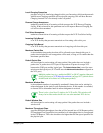
4
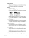
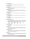
Maximum Packet Size
values are
128, 256, 512, 1024, 2048
, &
4096
.
Default Packet
Size
values are all of the above plus
16, 32
, &
64
. If X.25 will be run over this port, do
not configure a size greater than
2048
. If
4096
is specified, additional X.25 and frame
headers can make the frame too large.
2048
will not cause a problem, since larger frames
will simply be split, then re-assembled at the destination.
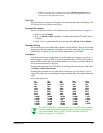
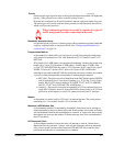
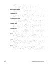
Mapped DLCI Number
is the Data Link Connection Identifier, which links the logical port to a logical con-
nection on the physical frame relay port. It must match the DLCI configured on the
device at the other end of the local (rather than end-to-end) connection.
Make sure no more than one of any interface type (logical port,
frame relay IP/IPX/LLC2 interface, or frame relay Bridge port)
is assigned the same DLCI.
Also make sure this DLCI is not configured as a Frame Relay
Backup DLCI or as part of an intra-nodal frame relay PVC.
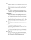
Blocked Port Flag
causes the logical port to be disabled (
Y
) or enabled (
N
) (only if the physical port is
also enabled) at node IPL. The port will remain in that state until this parameter is
changed or an on-line enable (
[B], [B], [C]
from the Main Menu) or disable (
[B], [B], [A]
from the Main Menu) is performed.
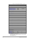
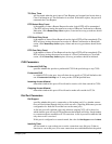
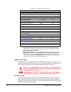
Default Packet Size 16–40 96
4
128
Maximum Window Size 2–7 7
Default Window Size 1–7 2
Maximum Throughput Class
see explanation none
Default Calling Address
0–15 characters none
T20 Restart Timer
(sec)
1–600 60
T21 Incoming Call Timer
(sec)
1–600 180
T22 Reset Timer
(sec)
1–6 00 60
T23 Clear Timer
(sec)
1–600 60
DTE Restart Retry Count 0–99 0
DTE Reset Retry Count 0–99 0
DTE Clear Retry Count 0–99 0
CUG Parameters
Preferential CUG Flag Y/N N
Preferential CUG 0–99 0
Incoming Access Allowed Y/N N
Outgoing Access Allowed Y/N N
Add/Change CUG
See explanation n/a
Display All CUGs
See explanation n/a
Delete CUG
See explanation n/a
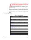
Table 8-2 Logical Port Parameters
Parameter Valid Values Default Value


