7-2 SmartSwitch 1800 4.0 User Guide, Rev 01
Frame Relay Backup
Frame relay virtual-circuit backup in the SmartSwitch 1800 provides frame relay
DLCIs with automatic backup protection in the event of LMI loss or port failure. (A
DLCI is considered down/inactive if level 1 is down. If LMI is used, the DLCI is also
considered inactive if not reported as active in a Full Status Message from the DCE.)
A physical frame relay port can be dedicated to providing backup DLCIs, or backups
can co-exist with "regular" DLCIs on a port.
In a backup configuration, one end is considered the "initiating" node and the other the
"remote" node. The initiating end is the one that will establish the backup link if it dis-
covers that the primary link is down. (A node can be the initiating node for some
backup configurations and the remote node for others.)
Any sessions in progress when a primary DLCI goes down will not be
transferred directly to the backup DLCI, but will be reset, then established
on the backup.
DLCIs used for backup on the initiating node are assigned to "backup groups," each
of which can contain up to ten backup DLCIs. A backup group is then assigned to one
or more "primary" DLCIs (the ones that will be backed up).
The basic procedure for configuring backup DLCIs is:
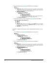
1. Configure all DLCIs that will be backed up or used as backups. All parameters
can be configured for each DLCI except specifying a
Backup Group Number
on a
primary DLCI (that will be backed up) on an "initiating" node (which will initiate
the switchover to a backup DLCI).
2. Configure backup groups. A backup group is one or more DLCIs that will act as
backup if the primary goes down.
3. Configure
Backup Group Number
s and related information for primary DLCIs.
This will assign a Backup Group to each primary DLCI.
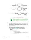
For each example in Figure 7-1, assume that Node 1 is a remote site and Node 2 is a
central site. Also assume that Node 1 will be the initiating node. On that node, the
primary DLCI is on port 2 and the backup is on port 0.


