Introduction to Database Configuration 3-3
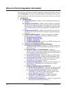
Frame Relay PVC Passthrough
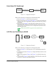
Figure 3-2 Configuration Example 2
Make sure the following are configured in each SmartSwitch 1800:
●
Protocols (Chapter 5), to load the frame relay protocol.
●
Physical frame relay port (Chapter 6 and Chapter 7). Configure the SmartSwitch
1800 port to the 3174 as logical DCE, and the port to the frame relay switch as
logical DTE.
●
Frame relay PVC (Chapter 7), which links the two frame relay ports in the
SmartSwitch 1800. The DLCIs are defined in the PVC record; if rate control
(CIR, BC, BE) will be enforced, be sure to configure those parameters in the
frame relay Port record.
Make sure each DLCI is supported on the attached device.
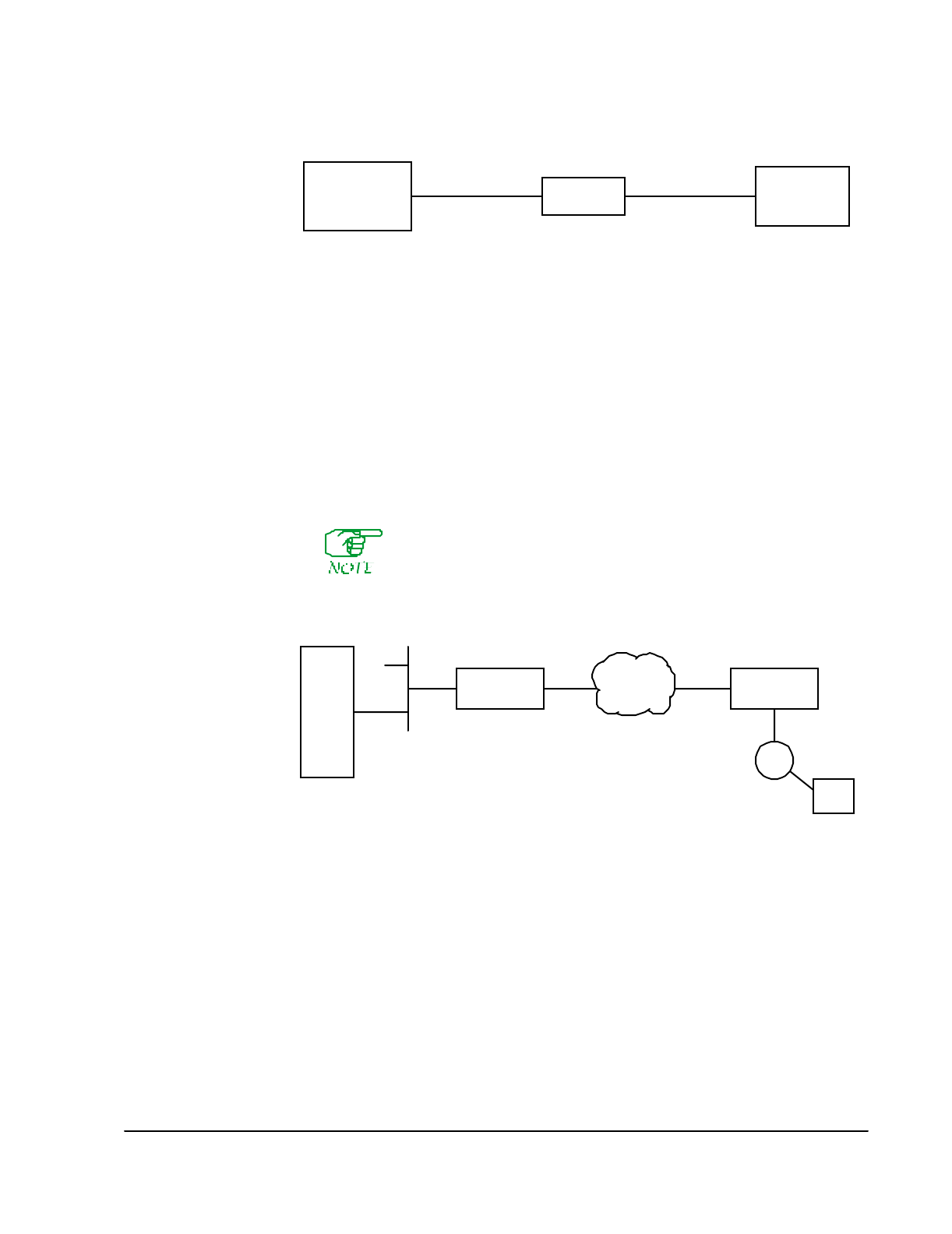
LLC2 PUs over Frame Relay to AS/400
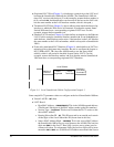
Figure 3-3 Configuration Example 3
Make sure the following are configured in each SmartSwitch 1800:
●
Protocols (Chapter 5), to load frame relay, LLC2, and Bridging (required for
LLC2).
●
LAN Interface parameters (Chapter 6), to configure the Ethernet interface on the
SmartSwitch.
●
Physical Port parameters (Chapter 6 and Chapter 7), to define the frame relay
port.
●
Virtual LAN ID (Chapter 9), which identifies a virtual bridge that connects the
internal LLC2 function to the Ethernet interface.
Frame Relay
Switch or
DCE FRAD
3174 Control
Unit Running
IP & SNA
SS1800
Frame Relay PVC Frame Relay PVC
AS/400
5494
Frame
Relay
Local
SS 1800
Remote
SS 1800


