


Voice Configuration Reference Information C-3
●
Voice Port 5 Configuration:
◆
# of Leading Digits to Delete = 0
.
◆
Forward Delay = 2
(.25 sec intervals)
◆
Forwarded Digit Type = DTMF
.
◆
Forwarded Output Digits = Ext
.
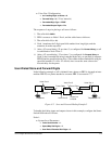
The sequence of steps in placing a call are as follows:
1. The caller dials
59222
.
2. PBX A connects to Node 1 Port 4, and the caller hears a dial tone.
3. The caller dials
77
(or
12
).
4. Node 1 translates the 2-digit speed dial number from long digits, and the
extension from the map table.
5. After a 1/2 second delay (.25 sec times 2, as configured for
Forward Delay
), a call
is established to Node 2 Port 5.
6. After a 1/2 second delay (.25 sec times 2, as configured for
Forward Delay
on
Node 2), the forwarded dial string (extended digits only, as specified) is output to
PBX B, and the specified phone rings. (The comma in the extended dial string for
speed dial number 12 is also 1/2 second, since it uses the same value as the
forward delay for the pause.
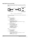
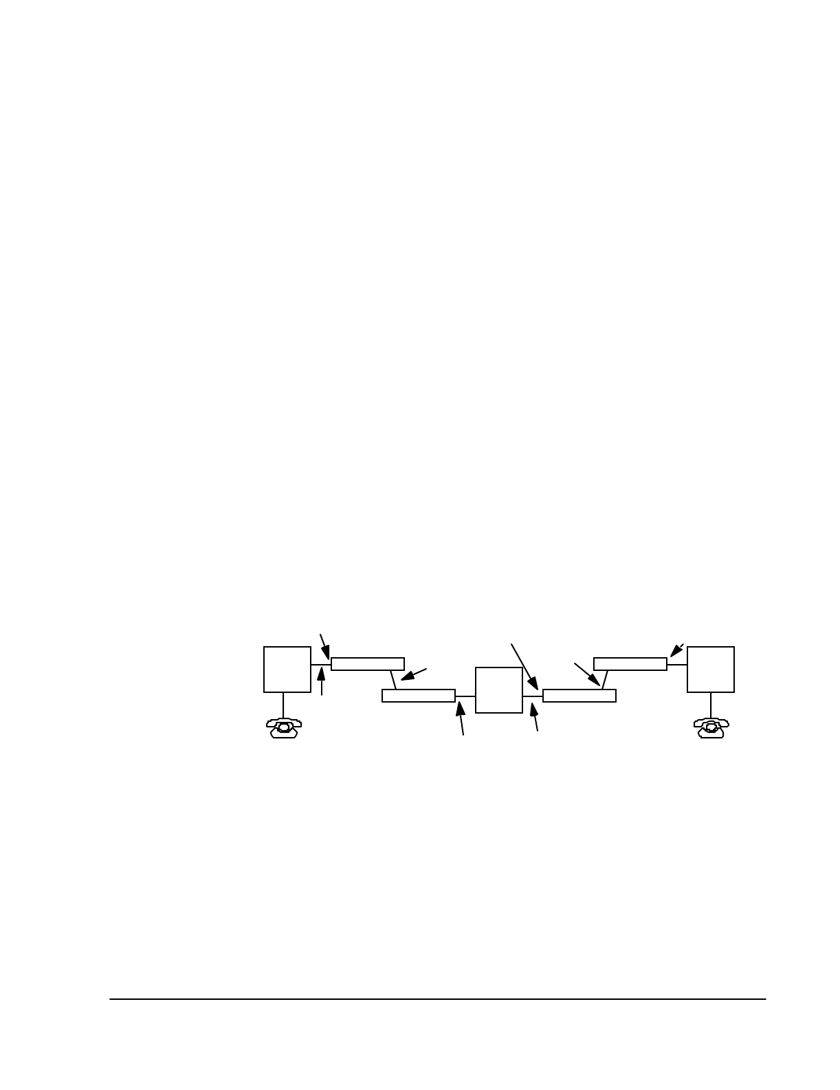
User-Dialed Store and Forward Digits
In the following example, a call is initiated from a phone on PBX A, through an inter-
mediate PBX B, to a phone attached to a remote PBX C at extension 777.
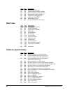
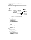
Figure C-2 Store and Forward Dialing Example 2
To handle the dialing inputs and outputs shown in this example, configure the Smart-
Switch 1800 nodes as follows:
Node 1:
●
System-Level Parameters:
◆
Voice Node Number
=
1
.
◆
Speed Map Dial Digits
=
2
.
◆
User Dialed Extended Dial Digits
=
5
.
Voice Port 5
Node 3
Phone line
# 59333
PBX A
Telephone #7777
Voice Port 4
Telephone
Node 1
Frame Relay
PBX C
PBX B
Voice Port 4
Voice Port 5
Node 4
Node 2
Frame Relay
Phone line
# 59111