FRM Configuring Frame Relay 7-3
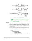
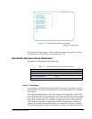
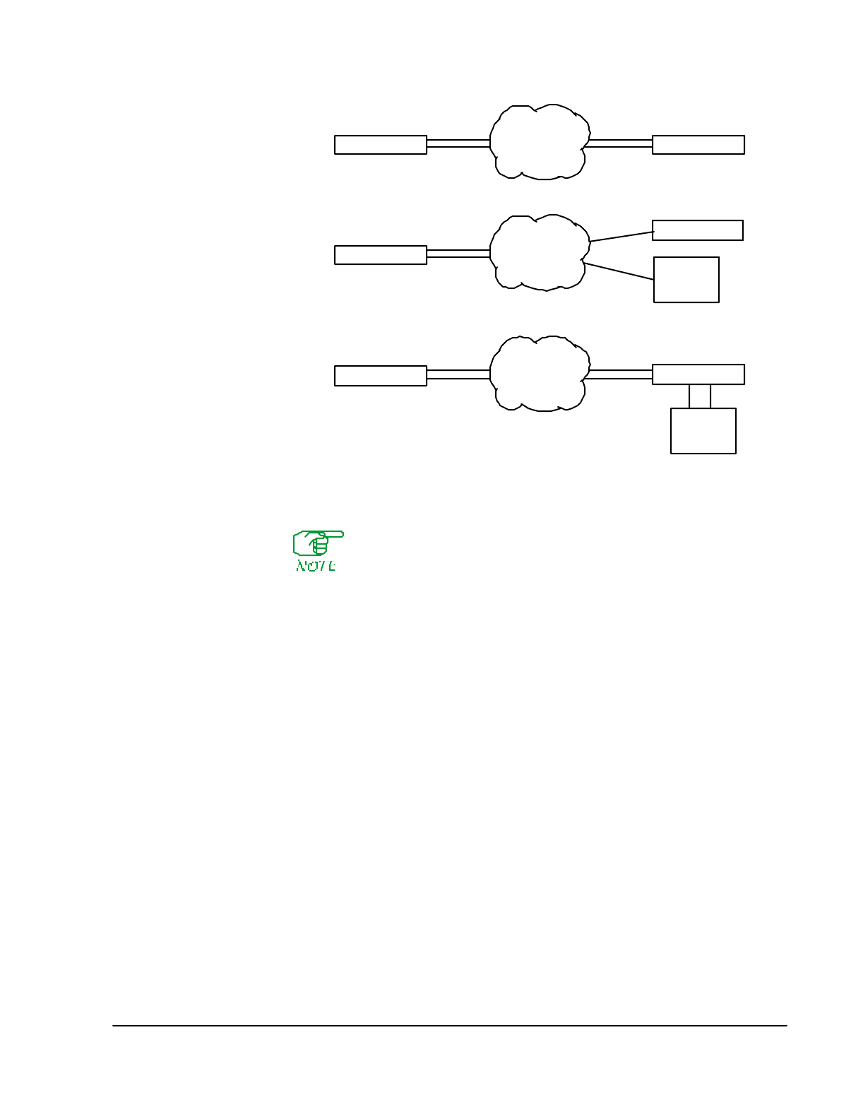
Figure 7-1 Frame Relay Backup Examples
Although each example shows a connection between a SmartSwitch
1800 and an FRX6000, connections can be between any two devices
in the family of SmartSwitch 1800, Frame Relay Module (FRM),
FRX4000, and FRX6000.
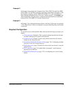
Example 1
In Example 1, the primary link is between Node 1/Port 2/DLCI 16 and Node 2/RLP
0/Port 0/DLCI 18. The DLCIs should be configured as described below. (The param-
eters are described later in this chapter.) Then if the primary link goes down, a con-
nection will automatically be established between Node 1/Port 0/DLCI 17 and Node
2/RLP 0/Port 4/DLCI 17.
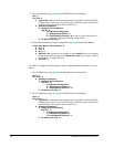
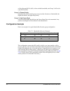
On Node 1, configure the following (as well as other parameters necessary for oper-
ation—this section deals only with the frame relay backup function):
1. Port Configuration (
[A], [C], [A]
from Main Menu) for the primary:
RLP: 0
RLP Port: 2
O Additional Parameters
D Configure DLCI Parameters
DLCI ID: 16
I DLCI Backup Configuration
A Backup Group Number: 10
(or any unused number except
0
)
B Enable Backup Protocol?: N
E For Backup Use Only: N
Example 1 Node 1
Example 2 Node 1
Example 3 Node 1
2,16
0,17
0,0,18
0,4,17
Node 2
Port,DLCI RLP,Port,DLCI
0,0,18
Node 2
2,16
0,17
2,16
0,17
0,0,18
0,4,17
Node 2
1, 3,22 1,4, 56
Other
Device
Other
Device


