


3-2 SmartSwitch 1800 4.0 User Guide, Rev 01
Most parameters can be specified and/or changed using the operations
described throughout the configuration portion of this manual; others, such
as port number, are defined by the hardware or specified during software
installation.
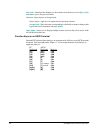
Configuration Examples
Serial Protocols over Frame Relay via Logical Ports
Below is a sample configuration and guidelines for configuring Logical Ports for
Annex G or RFC 1490 transmission over frame relay.
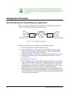
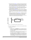
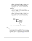
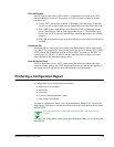
Figure 3-1 Configuration Example 1
Make sure the following are configured in each SmartSwitch 1800:
●
Protocols (Chapter 5), to load the serial protocols.
●
Physical Port (Chapter 6, plus Chapter 7 [Frame Relay], Chapter 8 [X.25],
Chapter 9 [SNA], Chapter 10 [BSC Interactive], Chapter 11 [BSC Batch],
Chapter 12 [Async], and Chapter 13 [Voice]).
●
Logical Port (Chapter 8) on the physical frame relay port that connects to the
network. (Note that logical ports are numbered 8–63, because 0–7 are the
physical ports.)
●
Voice interface (Chapter 13).
●
SVC Subscriber (Chapter 7 [Frame Relay], Chapter 8 [X.25], Chapter 9 [SNA],
Chapter 10 [BSC Interactive], Chapter 11 [BSC Batch], Chapter 12 [Async]),
and Chapter 13 [Voice]), which assign static addresses used to route the call
request packets of the physical access ports to the logical port and vice versa.
Subscriber addresses are based on the X.121 Called Address field.
●
Optional SVC subscriber records (static routes) for any attached X.25 DTEs.
These are needed to identify the attached DTEs’ X.121 Calling Addresses. If an
X.25 Call Request is received from the WAN link, the SmartSwitch 1800 needs
to know where to route the call.
SDLC
Async
BSCI
X.25
Sync passthru
SDLC
Async
BSCI
X.25
Sync passthru
Frame
Relay
SS1800
SS1800
Logical Ports