Configuring Node Defaults 4-3
Node Defaults Parameters
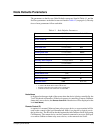
The parameters on the first two Node Defaults screens are listed in Table 4-1, and the
NetView parameters on the third screen are listed in Table 4-2 (on page 4-6). Descrip-
tions of most parameters follow each table.
1
Remember that the software sees uppercase as different from lowercase.
2
A value of
0
means that no status will be sent.
3
If
0
, the connection will remain active continuously.
4
Continuous retries until connection is established.
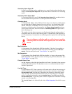
Node Name
is displayed at the upper right of the screen when the device is being controlled by the
"local" keyboard and monitor. (If the local operator is controlling a remote Cabletron
frame relay access device, the
Remote Control ID
of that device will be displayed as the
local
Node Name
.)
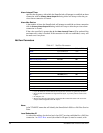
Remote Control ID
is required if a remote Cabletron frame relay access device or async terminal will be
used to take control of the local SmartSwitch 1800 (via a physical or logical port in
the local device). The ID will be checked against the called address fields of incoming
Call Requests. The remote device can be a terminal connected to an async PAD port
on a remote Cabletron frame relay access device, or the remote device itself.
Table 4-1 Node Defaults Parameters
Parameter Valid Values Default Value
Node Name
up to 8 characters none
Remote Control ID
0–15 digits none
Remote Control Pwd
0–15 characters
1
remote
File Transfer ID
0–15 digits none
File Transfer Pwd
0–15 characters
1
ftran
Collecting Node ID
0–15 digits none
Collecting Node Pwd
0–15 characters
1
alarms
Primary Alarm Output ID
1–15-digit address none
Primary Alarm Output Pwd
0–15 characters
1
alarms
Secondary Alarm Output ID
1–15-digit address none
Secondary Alarm Output Pwd
0–15 characters
1
alarms
Collecting Node Y/N N
Max Congestion 1–50
(%)
50
Min Congestion 1–50
(%)
25
Periodic Status Timer
0–30
(min)
2
1
Line Idle Timer
0–65535
(sec)
0
3
Alarm Autocall Timer
5–3600
(sec)
60
Alarm Max Retries 0– 99 0
(no max)
4


