


7-14 SmartSwitch 1800 4.0 User Guide, Rev 01
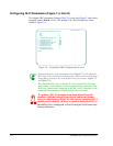
Frame Relay Port Parameters
1 If set to
Y
, no backup DLCIs on this port will be used (even if the port is enabled via
on-line port enable).
2 If one physical frame relay port will connect to several remote sites, be sure the line
speed is adequately higher that the speeds configured on the remote sites.
3 If this port will connect to a frame relay network, set
Logical DCE
to
N
. Also note that
one end of a frame relay backup connection must be configured as logical DCE.
4 Not applicable to CSU/DSU ports.
5 This parameter is relevant only if
Physical Port Interface
is something other than
RS-
232
and
Generate Clock
is
Y
.
6 Applicable only to CSU/DSU ports.
7 These parameters are relevant only if
Link Layer Management
is
LMI
or
ANNEXD
and
Logical DCE
is
N
.
8
N3
should be greater than or equal to
N2
.
9 If
Link Layer Management
is
none
, this parameter is irrelevant. (If
Link Layer Man-
agement
is changed to none from some other value, the default for
N2
will be left as it
was before the change.)
10
T2
should be greater than or equal to
T1
.
11 This parameter is relevant only if
Logical DCE
is
Y
.
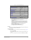
Table 7-3 Frame Relay Port Parameters
Parameter Valid Values Default Value
Port Type Frame Relay
not valid here
Physical Port Interface
see explanation see explanation
Blocked Port Flag Y/N
1
N
Line Speed
(bits per sec) see explanation
9600
2
Maximum Bytes per Frame 16–4096 1600
Logical DCE Y/N
3
Y
Generate Clock
4
Y/N Y
Rcv Clock (TT) from DTE
4,5
Y/N N
CSU/DSU Operating Mode
6
Normal/LDM Normal
RTS Control
6
Constant/External Constant
Link Layer Management None, LMI, ANNEXD None
N1 Polling Count
7
1–6 6
N2 Error Threshold
7
1–10
8
2
if
LMI
9
3
if
Annex D
9
N3 Monitored Events Count
7
1–10
8
4
T1 Link Integrity Timer
(sec)
7
5–30
10
10
T2 Polling Verification Timer
(sec)
11
5–30
10
15
Enable Outgoing Rate Control Y/N N
Enable Bandwidth Allocation Y/N N
For Backup Use Only? Y/N N
Automatic DCE Y/N N