


FRM Configuring Frame Relay 7-5
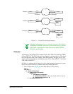
Example 2
In Example 2, the primary link is between Node 1/Port 2/DLCI 16 and Node 2/RLP
0/Port 0/DLCI 18. The DLCIs should be configured as described for Example 1 (with
the exception, naturally, of Node 2/RLP 0/Port 4/DLCI 17), with one difference—
when configuring Backup Group 10 (see step 3 under example 1), set
ProtEnab
to
N
.
Then if the primary link goes down, a connection will automatically be established
between Node 1/Port 0/DLCI 17 and the "Other Device."
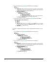
Example 3
In Example 3, the configuration between Node 1 and Node 2 is the same as in example
1. The "Other Device" must be configured to recognize both the primary and backup
connections.
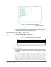
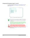
Required Configuration
To run frame relay in a SmartSwitch 1800, make sure the following are properly con-
figured:
●
Node parameters (Chapter 4). This is general configuration that must be done
no matter which protocols will be run in the node.
●
Loaded protocols (Chapter 5): frame relay and any others that will be trans-
mitted over the frame relay link.
●
Frame Relay Bandwidth Allocation Groups (page 7-6), if configuring multiple
protocols to run over a frame relay port.
●
Frame relay port(s) (page 7-9) that will connect to the user device(s), network,
and/or PVC(s).
●
PVC connections (page 7-20) which define "permanent" circuits between
physical ports in the node.
●
Frame Relay Backup Groups (page 7-22), if configuring one or more backup
DLCIs.