


13-12 SmartSwitch 1800 4.0 User Guide, Rev 01
The E&M types are described in Appendix C.
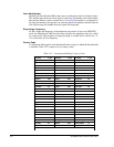
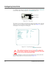
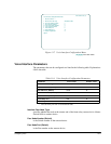
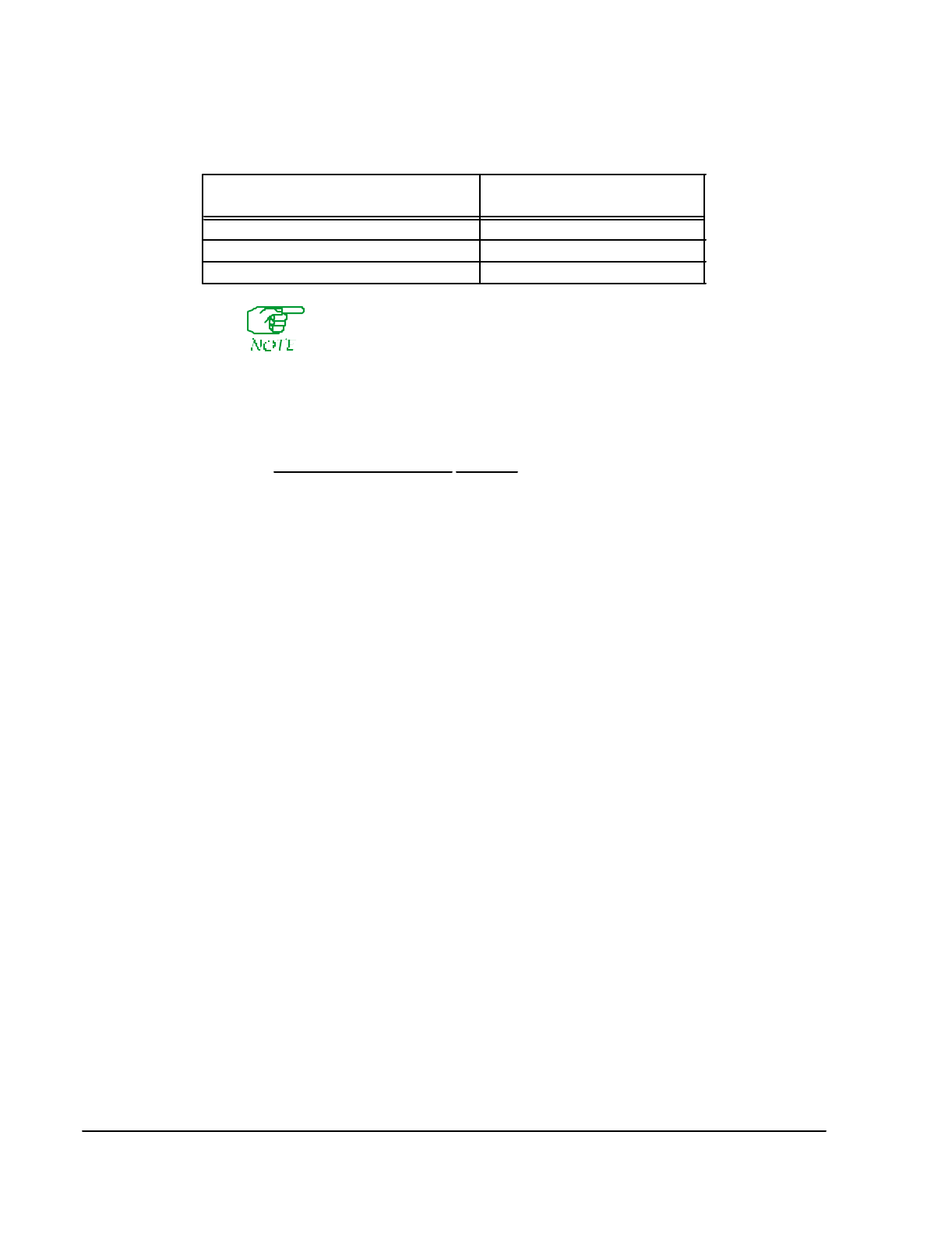
Interface
specifies (in conjunction with
Telephony Interface Type
) the type of interface that will
be used by the Voice channel. Valid selections are listed below:
Telephony Interface Type
Interface
OPX
(FXO)
Loop Start
SLT
(FXS)
Loop Start
E&M 4W E&M, 4W E&M TE, 2W E&M, 2W E&M TE
AC15 AC15A or AC15C
Loop Start
and
OPX
operating modes provide characteristics similar to those of a
central office.
Loop Start
and
SLT
operating modes provide characteristics similar to
those of a standard telephone set.
4W E&M
is the normal setting for a PBX E&M tie-line interface that uses one pair of
wires for the incoming voice signal and another pair of wires for the outgoing voice
signal.
2W E&M
is for an E&M tie line that uses a single pair of wires for both the
incoming and outgoing voice signal.
AC15A
or
AC15C
are 4-wire signaling systems used by PBXs to communicate with
each other and other PBX-like communications equipment
2W E&M
and
4W E&M
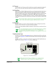
can be configured in these modes, via the switches on the front
of the SmartSwitch:
●
2W E&M
or
4W E&M
IS (Immediate Start), the industry standards for E&M oper-
ation.
●
2W E&M
or
4W E&M
DD (Delay Dial), which will cause the SmartSwitch will
expect an attached PBX to raise its M-lead to request a dial register. The Smart-
Switch will respond as follows: 1) toggle the E-lead, 2) send a dial register to
the PBX, 3) return the E-lead to its original state, and 4) wait for dial digits from
the PBX (no dial tone is transmitted to the PBX).
●
2W E&M
or
4W E&M
WS (Wink Start), which will cause the SmartSwitch will
expect an attached PBX to raise its M-lead to request a dial register. The Smart-
Switch will respond by sending a dial register to the PBX. When the PBX indi-
cates it is ready for dial digits (no dial tone is transmitted to the PBX), the
SmartSwitch will toggle the E-lead. When the E-lead returns to its original state,
the PBX will transmit dial digits to the SmartSwitch.
2W E&M TE
or
4W E&M TE
(Timed E&M) are specified, you can specify a delay at
which the E-Lead follows the M-Lead (See
TE Timer
below).
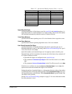
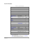
Table 13-5 E&M Switch Settings
E&M
Type
Voice Port 2
Sw. 8 Sw. 7 Sw. 6 Sw. 5
Voice Port 1
Sw. 4 Sw. 3 Sw. 2 Sw. 1
I UpUpDownDownUpUpDownDown
II Down Up Up Down Down Up Up Down
V UpDownUpUpUpDownUpUp