


22-2 SmartSwitch 1800 4.0 User Guide, Rev 01
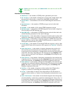
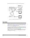
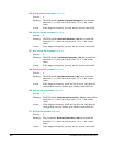
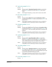
The following shows an example of a two-node event routing configuration.
Figure 22-1 Event Reporting Configuration Example
Alarm Buffer
Each node has a buffer where events are stored while waiting for transmission. When
a buffer reaches the percentage of full capacity specified by the parameter
Max Con-
gestion
, further events originating at that node are lost until the percentage of capacity
specified by the parameter
Min Congestion
is reached.
When the buffer reaches
Max Congestion
, the node adds the event message
Beginnin g
of congestion
to the buffer. No more events are put into the buffer until it has reached
Min Congestion
, at which time another message,
End of congestion, “n” events lost
, is
put into the buffer, and all events are again put into the buffer.
When the collecting node's event buffer reaches
Max Congestion
, events are held in the
originating nodes' buffers until the buffers reach
Max Congestion
or the collecting
node begins accepting events again.
Collecting Node ID =
222
Primary Alarm Output ID =
12345
Secondary Alarm Output ID =
C1
Network Mgmt.
Station with
Address
12345
Printer
Node 1
Collecting Node
Optional
Monitor
COM1
Alarms from
Node 2
Node 2
Optional
Async
Terminal