C-12 SmartSwitch 1800 4.0 User Guide, Rev 01
PTT/Telco Connectors and Cabling
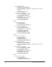
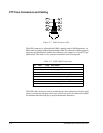
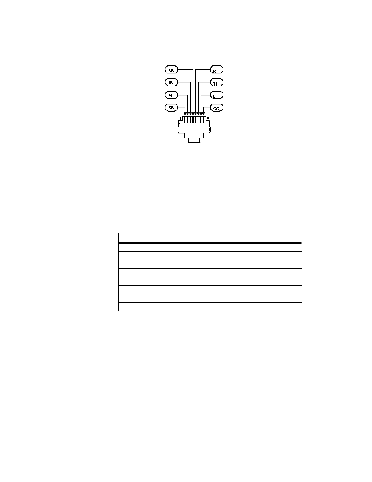
Figure C-7 RJ45 Connector Pins
The RJ45 connector on a SmartSwitch 1800 is mainly used for E&M operation. An
RJ45 cable is included with each SmartSwitch 1800. The cable end with the connector
plugs into the SmartSwitch, and the end with bare wire connects to a telco/PTT type
punch block. The cable is color-coded as described in the following table.
The RJ45 cable can also be used to provide the two-wire connection. For these appli-
cations, only the red and green wires (pins 4 and 5) are active; the other wires should
be insulated with electrical tape to prevent unwanted connections.
Table C-1 RJ45 Cable Connections
Pin Color Usage Description
1 Gray SB Return for M Signal
2 Orange M Control Signal from PBX
3 Black TR Voice from PBX (Transmit Ring)
4 Red RR Voice to PBX (Receive Ring) two-wire connection
5 Green RT Voice to PBX (Receive Tip) two-wire connection
6 Yellow TT Voice from PBX (Transmit Tip)
7 Blue E Control Signal to PBX
8 Brown SG Return for E Signal


