C-16 SmartSwitch 1800 4.0 User Guide, Rev 01
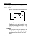
Type II
The Type II interface requires no common ground; instead, each of the two signals has
its own return. For the "E" signal, the tie line equipment permits current to flow from
the PBX; the current returns to the PBX's ground reference. Similarly, the PBX closes
a path for current to generate the "M" signal to the tie line equipment.
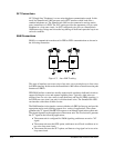
Type III
A variation of Type II, Type III uses the SG lead to provide common ground. With
this configuration, the PBX drops the "M" signal by grounding it, rather than by
opening a current loop.
Type IV
Type IV is symmetric and requires no common ground. Each side closes a current loop
to signal; the flow of current is detected via a resistive load to indicate the presence of
the signal.
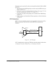
Type V
Type V is a simplified version of Type IV. This is also a symmetric interface, using
only two wires. Type V requires a common ground between the PBX and the tie line
equipment; this is provided via the SG leads.
E&M Grounding Considerations
Proper grounding is essential for correct operation of telephone equipment in E&M
applications. E&M signaling works by applying DC voltages to the "E" and M leads
in the process of connecting and disconnecting. Without a proper ground, the DC
voltages do not have a common point of reference, which can result in unintended or
sporadic signaling. To avoid grounding problems, certain conditions must be con-
sidered.
First, check the distance between the PBX and the SmartSwitch 1800. If the two are
not within close proximity, then their AC grounds may not be the same. If the Smart-
Switch and the PBX are in the same room, however, it is likely that they share the
same AC ground.
Second, in an E&M application, the common ground must be the telco/PTT ground.
This assures that the ground potential of the PBX telephone interface and the Smart-
Switch telephone interface are the same.
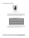
Based on the above conditions, grounding may be established directly or indirectly.
The direct method is to connect a grounding wire between the telco/PTT interfaces on
the PBX and SmartSwitch. You can do this by connecting the ground wire from the
PBX to pin 8 (SG) of the RJ45 connector on the SmartSwitch. This will establish the
same ground potential at both interfaces.
For various reasons, direct grounding is not always possible or practical. To establish
an indirect ground, make sure the telco/PTT grounds of the PBX and the SmartSwitch
are connected to their respective AC grounds. The AC grounds of the two devices
must be at the same potential as is usually true when both devices are located in close


