Configuring SNA 9-7
1
Set
Autocall
to
Y
for TPADs and
N
for HPADs.
2
If the PU will be used for SDLC-LLC2 conversion (at the local node, or at a remote node
via a logical or physical X.25 port), this must be
Y
.
3
In multiples of 4.
4
In Token Ring format.
5
Will override the value configured for the same parameter in the Node Defaults file, with
two exceptions—if
0
is configured in Port Configuration for
Priority
or
Bandwidth Allo-
cation Group
, the value in Node Defaults will apply.
6
Must be less than the value for
T1
to ensure that the remote link station will receive the
delayed acknowledgment before
T1
expires.
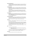
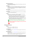
Port Type
specifies the protocol the port will support. Selecting this parameter will display a list
of all serial protocols loaded in the device.
Name
is used to identify the port to some manager devices.
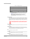
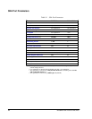
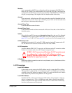
Table 9-2 SNA Port PU Parameters
Parameter Valid Values Default Value
PU Name
up to 10 characters none
Local Subscriber ID
0–15 characters none
Remote Subscriber ID
0–15 characters none
Maxdata
(Max I-Frm bytes/frame) 25–4105 265
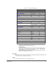
Autocall Y/N
1
N
Autocall Retry Time
(sec)
15–255 60
Autocall Retry Count 0–255 0
(indefinite)
Istatus Active, Inactive Active
LPDA Resource ID 0–255 0
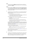
LLC2 Connection Y/N
2
N
L2DatMode Two-way Alternate,
Two-way Simultaneous Two-way Alternate
LLC2 Parameters
Local SAP Address 0–fc
(hex)
3
04
Local MAC Address 0–ffffffffffff
4
000000000000
IDBLK 0–fff 000
IDNUM 0–fffff 00000
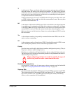
T1
(100 msec)
5
0–250 10
T2
(msec)
5
100–5000
6
100
Ti
(sec)
5
1–50 30
N3
5
1–127 1
Tw
5
1–127 1
N2
5
0–255 8
Priority
5
0–9 0
Bandwidth Allocation Group
5
0–16 0
Suppress XIDs Y/N N


