


7-10 SmartSwitch 1800 4.0 User Guide, Rev 01
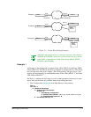
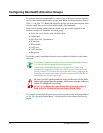
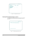
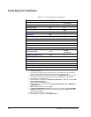
Figure 7-4 Frame Relay Port Screen 2
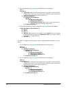
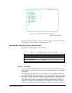
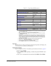
Reviewing DLCI Configuration (Figure 7-4, Item C)
To display the current configured DLCIs on the port, press
[C]
at the screen in Figure
7-4. A screen similar to the following information will be displayed for each con-
figured DLCI.
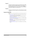
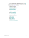
Figure 7-5 DLCI Configuration Review Screen
Node Name=node_xyz
Frame Relay Port Parameters (screen 2 of 2)
* Port: 0 Link State: Linkup
* I/ O : UNI VE RS AL
Database System Memory
A Enable Outgoing Rate Control Y Y
B Enab le Ban dwidth A llocation Y Y
C Review DLCI Configuration
D Configure DLCI Parameters
E View Le ar ned DLCI s
F For Backup Use Only N N
G Automatic D CE N N
Option:
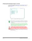
Node Name=n ode_xyz
Por t DLCI IC IR IBC IBE OCIR OBC O BE BE C N P ri P ro to
(Primary Info) Grp RRLP RPrt RDLCI SOT SBT TTH
2160000 0000N
2500000 0000N
10 050 25020
PgUp, PgDn , F2:R eview A ll DLCI s, F3:Exit