


Voice Configuration Reference Information C-13
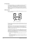
E&M Wiring
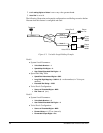
In a two-wire E&M application, connect red and green wires to the PBX's RT and RR
pair, respectively. The RT and RR pair carry voice or fax analog signals between the
SmartSwitch 1800 and the PBX.
In a four-wire E&M application, connect red and green wires to the PBX's RT and RR
pair, and black and yellow wires to the PBX's TR and TT pair, respectively. The RT
and RR pair carry voice or fax analog signals from the SmartSwitch 1800 to the PBX.
The TR and TT pair carry voice or fax analog signals from the PBX E&M tie trunk to
the SmartSwitch 1800.
Connect the signaling wires as indicated in the following table.
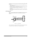
Normally, when PBX-to-PBX E&M tie trunks are installed, the "E" lead of one PBX
is normally crossed over and connected to the "M" lead of the other PBX, and vice
versa. In a multiplexer application the crossover is accomplished digitally, therefore,
when connecting a PBX to the system in E&M mode, the "E" and "M" leads of the
PBX connect to the "E" and "M" leads of the cable from the SmartSwitch straight
through, without crossing.
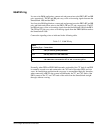
Table C-2 E&M Wiring
E&M
Signaling Type Connections
I, V
Connect Blue wire to the "E", Orange wire to the "M" and Brown wires to the
"SG" (or common ground) PBX leads.
II, IV
Connect Blue wire to the "E", Brown wire to the "SG", Orange wire to the "M"
and Gray wires to the "SB" PBX leads.
III
Connect Blue wire to the "E", Orange wire to the "M" and Gray wire to the
"SB" PBX leads. Connect Brown wire to "SG" or common ground.