


15-4 SmartSwitch 1800 4.0 User Guide, Rev 01
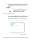
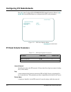
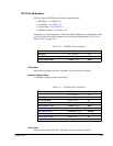
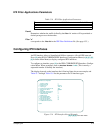
Figure 15-2 IPX SAP Filter Record
[A], [A],[E], [F],[B]
from Main Menu
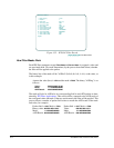
How Filter Masks Work
Each IPX filter parameter except
Filter Name
and
Server Name
is assigned a value and
an associated mask. The mask determines (by the process described below) whether
the filter will be applied to the packet.
The binary bits of the mask will be "ANDed" (0+0=0, 0+1=0, 1+1=1) to the value, as
in this example:
Assume the value (hex) is
1234
and the mask is
F000
. The binary "ANDing" is as
follows:
Value: 0001001000110100
Mask: 1111000000000000
AND Result: 0001000000000000
The mask will also be ANDed to its corresponding field in each IPX packet as deter-
mined by IPX Filter Applications. This result will be compared to the AND result of
the configured value and mask. If the two results match, the filter will be applied. This
process allows a number of packet field values to match the AND result of the mask
and value; for example:
Packet field =
1233
, Mask =
F000
: Packet field =
1237
, Mask =
F000
:
Binary value:
0001001000110011
Value:
0001001000110111
Mask:
1111000000000000
Mask:
1111000000000000
AND Result:
0001000000000000
AND Result:
0001000000000000
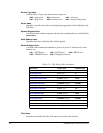
IPX Filter Definitions
* Filter Category 1–SAP
* Filter ID 1
A Filter Name filter_zxy
B Service Type Value 0004
C Service Type Mask 000f
D Server Name server_123
E Network Address Value ff00ac00
F Network Address Mask ffff0000
G Node Address Value 10ac45000001
H Node Address Mask ffffff000000
I Socket Address Value 4000
J Socket Address Mask f000
Option: