


Filtering/QoS Information
GR2K-GA-0014 1-97
Ver. 07-02
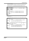
Specifies the queuing priority after having been changed. If this
parameter is specified and the output line is ATM, it is possible to set
the cell loss priority indication bit (CLP bit) of a cell transmitted by VC to
zero when the queuing priority is three or four, and to one when the
queuing priority is one or two. For setting the cell loss indication bit,
please refer to in GR2000 Configuration Commands, (universal CLI) Vol.
1.
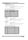
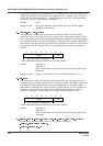
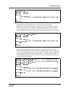
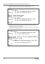
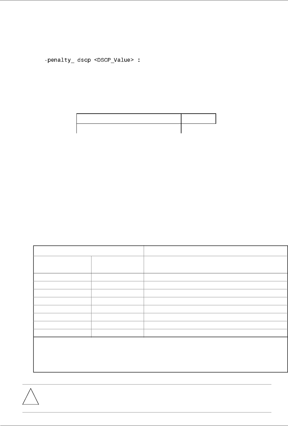
Specifies the DSCP rewriting value and controls QoS by using the
rewritten DSCP.
However, what is rewritten is the six high-order bits in the DSCP field.
The two low-order bits are ignored even if they are set.
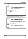
Default: When setting -upc: -penalty_drop
When setting -max_rate: -penalty_drop (Packets breaching the
maximum band are all discarded.)
When setting -min_rate: -discard 1 (Packets breaching the
minimum band are discarded more easily.)
Range of value: -penalty_dscp <DSCP_Value>: 0 to 63 (decimals)
-penalty_discard <No>: 1-4
(The smaller the value of the queuing priority, the more
preferentially the packet is discarded.)
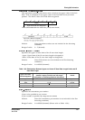
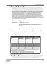
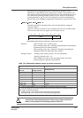
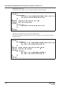
Table 1-53 Relationship between number of queues and priority
Setting Condition Range
Interface Using
this List
No. of Queue in
Output Interface
Queuing Priority
Input side -- 1-4
Output side 4 1-4
Output side 8 1-4
Output side 16 1-4
Output side 32 1-4
Output side 64 1-4
Output side 250 1-4 (*2)
Output side 1000 1-4 (*2)
*1: If value outside the range is set in output priority, the setting contents are nullified.
*2: If the QoS attribute of the output interface is the minimum band assurance (specified by kbps), the
flow control is executed as follows:
• Queuing priority 1 and 2: Flow control is executed at queuing priority 2.
• Queuing priority 3 and 4: Flow control is executed at queuing priority 4.
*
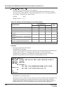
Note: Depending on setting of the important packet protection function, maximum band
restriction and minimum band guarantee, the number of entry used per list will be the
number of entry used per list for each setting as shown in Table 1-54.
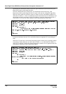
2
7
2
6
2
5
2
4
2
3
2
2
2
1
2
0
DSCP CU
High-order 6 bits are designated.
DSCP(Differentiated Services Code Point), CU(Current Unused)