


Code
or
Operation
Code. An eight-bit
word
used as an in-
struction
code
can
distinguish
between
256
alternative
actions, more
than
adequate
for
most
processors.
The
processor fetches an
instruction
in
two
distinct
operations. First,
the
processor
transmits
the
address in its
Program
Counter
to
the
memory.
Then
the
memory
returns
the
addressed
byte
to
the
processor.
The
CPU stores
this
instruction
byte
in a register
known
as
the
Instruction
Register, and uses it
to
direct
activities
during
the
remainder
of
the
instruction
execution.
The
mechanism
by
which
the
processor
translates
an
instruction
code
into
specific processing
actions
requires
more
elaboration
tha~
we
can here
afford.
The
concept,
however,
should
be intuitively clear
to
any
logic designer.
The
eight bits
stored
in
the
instruction
register can be de-
coded
and
used
to
selectively activate
one
of
a
number
of
output
lines,
in
this
case
up
to
256
lines. Each line repre-
sents a
set
of
activities associated
with
execution
of
a par-
ticular instruction code.
The
enabled
line can be
combined
w\th selected timing pulses,
to
develop electrical signals
that
can
then
be used
to
initiate specific actions.
This
transla-
tion
of
code
into
action
is
performed
by
the
Instruction
Decoder
and
by
the
associated
control
circuitry.
An eight-bit
instruction
code
is
often
sufficient
to
specify a particular processing
action.
There
are times, how-
ever,
when
execution
of
the
instruction
requires
more
infor-
mation
than
eight
bits can convey.
One
example
of
this
is
when
the
instruction
refer-
ences a
memory
location.
The
basic
instruction
code iden-
tifies
the
operation
to
be
performed,
but
cannot
specify
the
object
address as well.
In
a case like this, a
two-
or
three-
byte
instruction
must
be used. Successive
instruction
bytes
are
stored
in sequentially
adjacent
memory
locations,
and
the
processor
performs
two
or
three
fetches
in
succession
to
obtain
the
full
instruction.
The
first
byte
retrieved
from
memory
is
placed in
the
processor's
instruction
register,
and
subsequent
bytes
are placed in
temporary
storage;
the
pro-
cessor
then
proceeds
with
the
execution
phase.
Such
an
instruction
is
referred
to
as Variable Length.
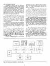
Address Register(s):
A CPU
may
use a register
or
register-pair
to
hold
the
address
of
a
memory
location
that
is
to
be accessed
for
data.
If
the
address register
is
Programmable,
(Le., if
there
are instructions
that
allow
the
programmer
to
alter
the
contents
of
the
register)
the
program can
"build"
an ad-
dress in
the
address register
prior
to
executing
a Memory
Reference
instruction
(Le.,
an
instruction
that
reads
data
from
memory,
writes
data
to
memory
or
operates
on
data
stored
in
memory).
Arithmetic/Logic
Unit
(ALU):
All processors
contain
an
arithmetic/logic
unit,
which
is
often
referred
to
simply as
the
ALU.
The
ALU,
as its
name implies,
is
that
portion
of
the
CPU
hardware
which
1-3
performs
the
arithmetic
and logical
operations
on
the
binary
data.
The
ALU
must
contain
an
Adder
which
is
capable
of
combining
the
contents
of
two
registers
in
accordance
with
the
logic
of
binary
arithmetic.
This
provision
permits
the
processor
to
perform
arithmetic
manipulations
on
the
data
it
obtains
from
memory
and
from
its
other
inputs.
Using
only
the
basic
adder
a capable
programmer
can
write
routines
which will
subtract,
multiply
and
divide,
giv-
ing
the
machine
complete
arithmetic
capabilities.
In
practice,
however,
most
ALUs
provide
other
built-in
functions,
in-
cluding
hardware
subtraction,
boolean
logic
operations,
and
shift capabiIities.
The
ALU
contains
Flag Bits
which
specify certain
conditions
that
arise
in
the
course
of
arithmetic
and
logical
manipulations. 'Flags
typically
include Carry,
Zero,
Sign,
and
Parity. It
is
possible
to
program
jumps
which are condi-
tionally
dependent
on
the
status
of
one
or
more
flags. Thus,
for
example,
the
program
may
be designed
to
jump
to
a
special
routine
if
the
carry
bit
is
set
following an
addition
instruction.
Control
Circuitry:
The
control
circuitry
is
the
primary
functional
unit
within
a CPU. Using
clock
inputs,
the
control
circuitry
maintains
the
proper
sequence
of
events
required
for
any
processingtask.
After
an
instruction
is
fetched
and
decoded,
the
control
circuitry
issues
the
appropriate
signals
(to
units
both
internal
and
external
to
the
CPU) for initiating
the
proper
processing
action.
Often
the
control
circuitry
will be
capable
of
responding
to
external
signals,
such
as
an
inter-
rupt
or
wait
request.
An
Interrupt
request
will cause
the
control
circuitry
to
temporarily
interrupt
main program
execution,
jump
to
a special
routine
to
service
the
interrupt-
ing device,
then
automatically
return
to
the
main
program.
A Wait
request
is
often
issued
by
a
memory
or
I/O
element
that
operates
slower
than
the
CPU.
The
control
circuitry
will idle
the
CPU until
the
memory
or
I/O
port
is
ready
with
the
data.
COMPUTER OPERATIONS
There
are
certain
operations
that
are
basic
to
almost
any
computer.
A
sound
understanding
of
these
basic opera-
tions
is
a necessary
prerequisite
to
examining
the
specific
operations
of
a
particular
computer.
Timing:
The
activities
of
the
central
processor are cyclical.
The
processor
fetches
an
instruction,
performs
the
operations
required,
fetches
the
next
instruction,
and
so
on.
This
orderly
sequence
of
events
requires precise
timing,
and
the
CPU
therefore
requires a
free
running
oscillator
clock which
furnishes
the
reference
for
all processor
actions.
The
com-
bined
fetch
and
execution
of
a single
instruction
is
referred
to
as
an
Instruction
Cycle.
The
portion
of
a cycle identified