


SCHOTTKY BIPOLAR
8212
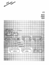
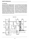
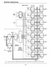
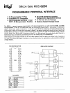
VIII. 8008 System
This shows the 8212 used in
an
8008 microcomputer
system. They are used to multiplex the data from
three different sources onto the 8008 input data bus.
The three sources
of
data are: memory data, input
data, and the interrupt instruction. The
8212
is also
used as the uni-directional bus driver to provide a
proper drive to the address latches (both low order
and high order are also 8212's) and to provide ade-
quate drive to the output data bus. The control of
these six 8212's in the 8008 system is provided by
the control logic and clock generator circuits. These
circuits consist of flip-flops, decoders, and gates to
generate the control functions necessary for
8008
microcomputer systems. Also note that the input
data port has a strobe input. This allows the proces-
sor to
be
interrupted from the input port directly.
The control of the input bus consists of the data bus
input signal, control logic, and the appropriate
status signal for bus discipline whether memory
read, input,
or
interrupt acknowledge. The combina-
tion of these four signals determines which one of
these three devices will have access to the input
data bus. The bus driver, which is implemented
in
an
8212,
is also controlled by the control logic and
clock generator so it can be
3-stated when neces-
sary and also
as
a control transmission device to
the address latches. Note: The address latches can
be
3-stated for DMA purposes and they provide
15
miHi
amps drive, sufficient for large bus systems.
8008 SYSTEM
INPUT
DATA
BUS
BUS
DRIVER
ADDRESS
LATCHES
HIGH ORDER
(6 BITS)
LOW
ORDER
(8 BITS)
------vee
I
••••••
DATA
BUS
OUT
(04,5,6,7)
t l
SYNC
INT
READY
~
¢2
I
00-07
¢1
L-..----......----0111
MEM READ
"""--'----------4----rJIII
INPUT
---------4-----oIIIINT
ACK I
-----......-----tlDATA
BUS
IN
b---------.
..
WR
'-f--I------------.q,NT
REO. I
..
OUT
WAIT
REQ.------l.MI
I
'-
J
CONTROL LOGIC
& CLOCK GEN.
8212
INPUT
DATA
INPUT
STROBE
MEMORY
DATA
INTERRUPT
INSTRUCTION
5-106