


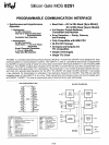

SILICON GATE MOS
8251
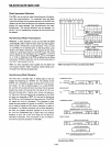
DETAILED OPERATION DESCRIPTION
General
The complete functional definition
of
the
8251
is
program-
med by the systems software. A set
of
control words must
be sent out by
the
CPU
to
initialize
the
8251
to
support
the
desired communications format. These control words will
program the: BAUD RATE, CHARACTER LENGTH,
NUMBER
OF STOP BITS, SYNCHRONOUS
or
ASYNCH-
RONOUS OPERATION, EVEN/ODD PARITY etc.
In
the
Synchronous Mode, options are also provided
to
select either
internal
or
external character synchronization.
Once
programmed~
the
8251
is
ready
to
perform its com-
munication functions.
The
TxRDY
output
is
raised
"high"
to
signal
the
CPU
that
the
8251
is
ready
to
receive a char-
acter. This
output
(TxRDY)
is
reset automatically when
the
CPU
wdtes
a character into
the
8251. On
the
other
hand,
the
8251 receives serial
data
from
the
MODEM
or
I/O de-
vice, upon receiving an entire character
the
RxRDY
output
is
raised "high"
to
signal
the
CPU
that
the
8251 has a com-
plete character ready for
the
CPU
to
fetch.
Rx
R
DY
is
reset
automatically upon
the
CPU
read operation.
The 8251 cannot begin transmission until
the
TxEN
(Trans-
mitter Enable) bit
is
set in
the
Command Instruction and
it has received a Clear
To
Send (CTS) input.
The
TxD out-
put
will
be held
in
the
marking
state
upon Reset.
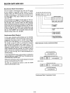
Programming the 8251
Prior
to
starting data transmission
or
reception,
the
8251
must be loaded with a set
of
control words generated by
the
CPU.
These control signals define
the
complete func-
tional definition
of
the
8251 and
must
immediately follow
a Reset operation (internal
or
external).
The control words are split into
two
formats:
1.
Mode Instruction
2. Command Instruction
Mode Instruction
This format defines the general operational characteristics
of
the
8251. It must follow a Reset operation (internal or
external). Once
the
Mode instruction has been written into
the 8251 by
the
CPU, SYNC characters
or
Command
in-
structions may be inserted.
Command Instruction
This format defines a status word
that
is
used
to
control
the actual operation
of
the
8251.
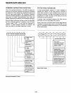
Both the Mode and Command instructions must conform
to
a specified sequence for proper device operation. The Mode
Instruction must be inserted immediately following a Reset
operation, prior
to
using
the
8251
for
data communication.
All
control words written into
the
8251 after
the
Mode
In-
struction will load
the
Command Instruction. Command
In-
structions can be written into
the
8251
at
any time in
the
data block during
the
operation
of
the
8251.
To
return
to
the
Mode Instruction
format
a
bit
in
the
Command Instruc-
tion word can be set
to
initiate an internal Reset operation
which automatically places
the
8251 back into
the
Mode
Instruction format. Command Instructions
must
follow the
Mode Instructions
or
Sync characters.
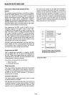
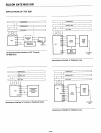
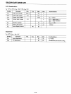
C/O:: 1
MODE INSTRUCTION
C/O:: 1
SYNC CHARACTER 1
} SYNC MODE
C/o
= 1
SYNC CHARACTER 2
ONLY·
C/D:: 1
COMMAND INSTRUCTION
C/D:: 0
DATA
C/o::
1 COMMAND INSTRUCTION
C/o:;;: 0
DATA
C/O::::
1 COMMAND INSTRUCTION
·The
second
SYNC character
is
skipped
if
MODE instruction
has
programmed the 8251
to
single character Internal SYNC
Mode.
Both SYNC characters
are
skipped
if
MODE instruction
has
programmed the
8251
to
ASYNC mode.
Typical Data Block
5-139