


be synchronized
with
the
pulses
of
the
driving clock.
Thus,
the
duration
of
all
states
are integral multiples
of
the
clock
period.
To
summarize
then,
each clock period marks a state;
three
to
five
states
constitute
a machine cycle;
and
one
to
five machine cycles comprise an instruction cycle. A full
instruction cycle requires
anywhere
from
four
to
eight-
teen states
for
its
completion,
depending
on
the
kind
of
in-
struction involved.
Machine Cycle Identification:
With
the
exception
of
the
DAD instruction,
there
is
just
one
consideration
that
determines
how
many
machine
cycles are required
in
any
given instruction cycle:
the
num-
ber
of
times
that
the
processor
must
reference a
memory
address
or
an addressable peripheral device,
in
order
to
fetch
and
execute
the
instruction. Like
many
processors,
the
8080
is
so
constructed
that
it
can
transmit
only
one
address per machine cycle.
Thus,
if
the
fetch
and
execution
of
an instruction requires
two
memory
references,
then
the
instruction cycle associated with
that
instruction consists
of
two
machine cycles.
If
five such references are called for,
then
the
instruction cycle
contains
five machine cycles.
Every instruction cycle has
at
least
one
reference
to
memory,
during which
the
instruction
is
fetched.
An
in-
struction cycle
must
always have a
fetch,
even
if
the
execu-
tion
of
the
instruction requires no
further
references
to
memory.
The
first machine cycle
in
every instruction cycle
is
therefore
a FETCH. Beyond
that,
there
are no fast rules.
It depends
on
the
kind
of
instruction
that
is
fetched.
Consider
some
examples.
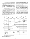
The
add-register (ADD
r)
instruction
is
an instruction
that
requires
on
Iy
a single
machine cycle (FETCH)
for
its
completion.
In
this
one-byte
instruction,
the
contents
of
one
of
the
CPU's six general
purpose registers
is
added
to
the
existing
contents
of
the
accumulator. Since all
the
information necessary
to
execute
the
command
is
contained
in
the
eight bits
of
the
instruction
code,
only
one
memory
reference
is
necessary.
Three
states
are used
to
extract
the
instruction from
memory,
and
one
additional
state
is
used
to
accomplish
the
desired
addition.
The
entire
instruction cycle
thus
requires
only
one
machine
cycle
that
consists
of
four
states,
or
four
periods
of
the
ex-
ternal clock.
Suppose
now, however,
that
we wish
to
add
the
con-
tents
of
a specific
memory
location
to
the
existing
contents
of
the
accumulator
(ADD M).
Although
this
is
quite
similar
in
principle
to
the
example
just
cited, several additional
steps will be used. An
extra
machine cycle will be used,
in
order
to
address
the
desired
memory
location.
The
actual sequence
is
as follows. First
the
processor
extracts
from memory
the
one-byte
instruction word ad-
dressed
by
its program
counter.
This
takes
three
states.
The
eight-bit
instruction
word
obtained
during
the
FETCH
machine cycle
is
deposited
in
the
CPU's
instruction
register
and used
to
direct
activities during
the
remainder
of
the
instruction cycle. Next,
the
processor sends
out,as
an address,
2-4
the
contents
of
its
Hand
L registers.
The
eight-bit data
word
returned
during
this
MEMORY READ machine cycle
is
placed
in
a
temporary
register inside
the
8080
CPU.
By
now
three
more
clock periods (states) have elapsed. In
the
seventh and final state,
the
contents
of
the
temporary
regis-
ter
are added
to
those
of
the
accumulator.
Two
machine
cycles, consisting
of
seven
states
in
all,
complete
the
"ADD
Mil
instruction cycle.
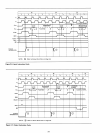
At
the
opposite
extreme
is
the
save
Hand
L registers
(SHLD) instruction, which requires five machine cycles.
During an
"SH
LD"
instruction
cycle,
the
contents
of
the
processor's
Hand
L registers are
deposited
in
two
sequen-
tially
adjacent
memory
locations;
the
destination
is
indi-
cated by
two
address
bytes
which are stored
in
the
two
memory locations immediatelyfollowing
the
operation
code
byte.
The
following sequence
of
events occurs:
(1) A FETCH machine cycle, consisting
of
four
states. During
the
first
three
states
of
this
machine cycle,
the
processor
fetches
the
instruc-
tion
indicated
by
its program
counter.
The
pro-
gram
counter
is
then
incremented.
The
fourth
state
is
used
for
internal instruction decoding.
(2) A MEMORY READ machine cycle, consisting
of
three
states. During
this
machine cycle,
the
byte
indicated by
the
program
counter
is
read
from
memory
and
placed
in
the
processor's
Z register.
The
program
counter
is
incremented
again.
(3)
Another
MEMORY READ
machine
cycle, con-
sisting
of
three
states, in which
the
byte
indica-
ted
by
the
processor's
program
counter
is
read
from
memory
and
placed
in
the
W register.
The
program
counter
is
incremented,
in
anticipation
of
the
next
instruction
fetch.
(4) A MEMORY WRITE
machine
cycle,
of
three
states, in which
the
contents
of
the
L register
are transferred
to
the
memory
location
pointed
to
by
the
present
contents
of
the
Wand
Z regis-
ters.
The
state
following
the
transfer
is
used
to
increment
the
W,Z register pair so
that
it indi-
cates
the
next
memory
location
to
receive
data.
(5) A MEMORY WRITE machine cycle,
of
three
states,
in
which
the
contents
of
the
H register
are
transferred
to
the
new
memory
location
pointed
to
by
the
W,Z register pair.
In
summary,
the
"SHLD"
instruction
cycle
contains
five machine cycles
and
takes
16
states
to
execute.
Most instructions fall somewhere
between
the
ex-
tremes typified by
the
"ADD
r"
and
the
"SHLD"
\ostruc-
tions.
The
input
(INP)
and
the
output
(OUT) instructions,
for
example,
require
three
machine cycles: a FETCH,
to
obtain
the
instruction; a MEMORY READ,
to
obtain
the
address
of
the
object
peripheral;
and
an INPUT
or
an OUT-
PUT machine cycle,
to
complete
the
transfer.