


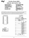

SCHOTTKY BIPOLAR
8212
.
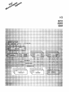
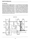
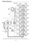
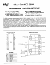
IX. 8080 System
This drawing shows the
8212
used in the
I/O
section
of
an
8080
microcomputer system. The system con-
sists of 8 input ports, 8 output ports, 8 level priority
systems, and a bidirectional bus driver. (The data
bus within the system is darkened for emphasis).
Basically, the operation would be
as
follows: The 8
ports, for example, could be connected to 8 key-
boards, each keyboard having its own priority level.
The keyboard could provide a strobe input of its
own which would clear the service request flip-flop.
The INT signals are connected to
an
8 level priority
encoding circuit. This circuit provides a positive
true level to the central processor (lNT) along with
a three-bit code to the interrupt instruction port for
the generation of RESTART instructions. Once the
processor has been interrupted and
it
acknowledges
the reception of the interrupt, the Interrupt Acknowl-
edge signal is generated. This signal transfers data
in
the form of a RESTART instruction onto the buf-
fered data bus. When the DBIN signal is true this
RESTART instruction is gated into the microcom-
puter, in this case, the 8080 CPU. The 8080 then per-
forms a software controlled interrupt service routine,
saving the status of its current operation in the
push-down stack and performing
an
INPUT instruc-
tion. The INPUT instruction thus sets the INP status
bit, which is common
to
all input ports.
Also present is the address of the device on the
8080 address bus which in this system is connected
to
an
8205, one out
of
eight decoder with active low
outputs. These active low outputs will enable one
of
the input ports, the one that interrupted the proces-
sor, to put its data onto the buffered data bus to
be
transmitted to the
CPU
when the data bus input
signal is true. The processor can also output data
from the 8080 data bus to the buffered data bus
when the data bus input signal is false. Using the
same address selection technique from the
8205
decoder and the output status bit, we can select
with this system one
of
eight output ports to trans-
mit the data to the system's output device structure.
Note: This basic
I/O
configuration for the 8080 can
be expanded to
256
input devices and 256 output
devices all using 8212 and,
of
course, the appropri-
ate decoding.
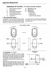
Note that the 8080 is a 3.3-volt minimum high input
requirement and that the 8212 has a 3.65-volt mini-
mum high output providing the designer with a
350
milli volt noise margin worst case for 8080 systems
when using the
8212.
5-107