


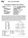

SILICON GATE MOS 8251
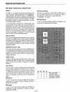
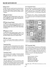
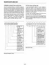
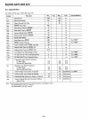
Mode Instruction Definition
The 8251 can be used for either Asynchronous
or
Synchro-
nous
data
communication.
To
understand how
the
Mode
Instruction defines
the
functional operation
of
the
8251
the
designer can best view
the
device as
two
separate components
sharing
the
same package. One Asynchronous
the
other
Synchronous.
The
format
definition can be changed lion
the
fly"
but
for
explanation purposes
the
two
formats will
be isolated.
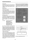
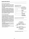
Asynchronous Mode (Transmission)
Whenever a
data
character
is
sent
by
the
CPU
the
8251
automatically adds a
Start
bit
(low level) and
the
program-
med
number
of
Stop
bits
to
each character. Also, an even
or
odd Parity
bit
is
inserted prior
to
the
Stop
bit(s),
as
de-
fined
by
the
Mode Instruction.
The
character
is
then trans-
mitted as a serial
data
stream on
the
TxD
output.
The
serial
data
is
shifted
out
on
the
falling edge
of
TxC
at
a rate equal
to
1,
1/16,
or
1/64
that
of
the
TxC,
as
defined
by
the
Mode
Instruction. 8 REAK characters can be continuously
sent
to
the
TxD if commanded
to
do
so.
When no
data
characters have loaded into
the
8251
the
TxD
output
remains
"high"
(marking) unless a Break (con-
tinuously low) has been programmed.
I
~
I8
1
I
EP
I
PEN
I
~
1 L
1
1
B21
B
1
I
L
BAUD RATE FACTOR
0 1 0 1
0 0
1 1
SYNC
(1X) (16X) (64X)
MODE
CHARACTER LENGTH
0
1
0 1
0
0 1 1
5 6
7
8
BITS
BITS BITS BITS
PARITY
ENABLE
1= ENABLE
0=
DISABLE
EVEN PARITYGENERATION/CHE
1= EVEN
0=000
NUMBER OF
STOP
BITS
0
1 0 1
0
0 1 1
INVALID
1
1%
2
BIT
BITS BITS
Mode
Instruction
Format, Asynchronous Mode
CK
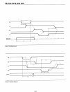
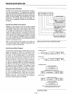
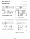
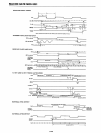
Asynchronous Mode (Receive)
TRANSMITTER OUTPUT
ASSEMBLED SERIAL
DATA
OUTPUT (TxD)
ST6;"l
BrTS
L
ST~
BITS L
STO[]
BITS
......
---..a---...&----f
DATA:B\-IT_S_....-.
__
...
SERIAL
DATA
INPUT (RxD)
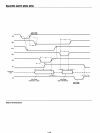
CPU
BYTE (5·8 BITS/CHAR)
DATA
C~~RACTER
DATA
CHARACTER
START
BIT
RECEIVE FORMAT
RxD
TRANSMISSION FORMAT
RECEIVER INPUT
TxD MARKING
The RxD line
is
normally high. A falling edge
on
this line
triggers
the
beginning
of
a START bit.
The
validity
of
this
START bit
is
checked by again strobing
this
bit
at
its nom-
inal center. If a low
is
detected again, it
is
a valid START
bit, and
the
bit
counter
will
start
counting.
The
bit
counter
locates
the
center
of
the
data bits,
the
parity bit (if it ex-
ists)
and
the
stop
bits. If parity error occurs,
the
parity er-
ror flag
is
set. Data and parity bits are sampled on
the
RxD
pin with
the
rising edge
of
RxC.
If
a low level
is
detected
as
the
STOP bit,
the
Framing Error flag will be set.
The
STOP
bit signals
the
end
of
a character. This character
is
then
loaded into
the
parallel I/O buffer
of
the
8251.
The
RxRDY
pin
is
raised
to
signal
the
CPU
that
a character
is
ready
to
be fetched. If a previous character has
not
been fetched by
the
CPU,
the
present character replaces it
in
the
I/O buf-
fer, and
the
OVERRUN flag
is
raised (thus
the
previous
character
is
lost). All
of
the
error flags can be reset by a
command instruction.
The
occurrence
of
any
of
these er-
rors will
not
stop
the
operation
of
the
8251.
DATA
CHARACTER
STOtJ
BITS
f----.&.---.Iooo----t
CPU
BYTE (5·8 BITS/CHAR)*
DATA
CH:;ACTER
*NOTE: IF CHARACTER LENGTH
IS
DEFINED
AS
5,6
OR
7
BITSTHE UNUSED BITS ARE
SET
TO
"ZERO".
Asynchronous Mode
5-140