


This
chapter
will illustrate, in detail,
how
to
interface
the
8080
CPU
with
Memory
and
I/O. It will also
show
the
benefits and
tradeoffs
encountered
when
using a variety
of
system architectures
to
achieve higher
throughput,
de-
creased
component
count
or
minimization
of
memory
size.
8080
Microcomputer system design lends itself
to
a
simple,
modular
approach.
Such
an
approach
will yield
the
designer a reliable, high
performance
system
that
contains
a
minimum
component
count
and
is
easy
to
manufacture
and
maintain.
Control Bus A uni-directional
set
of
signals
that
indicate
the
type
of
activity in
current
process.
Type
of
activities: 1. Memory Read
2. Memory Write
3. I/O Read
4. I/O Write
5. I
nterrupt
Acknowledge
CPU
Module* Contains
the
Central Processing Unit, system
timing
and
interface
circuitry
to
Memory
and
I/O devices.
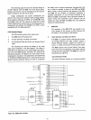
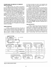
The
overall system can be
thought
of
as a simple
block diagram.
The
three
(3) blocks in
the
diagram repre-
sent
the
functions
common
to
any
computer
system.
*"Module"
refers
to
a
functional
block,
it
does
not
ref-
erence a printed circuit
board
manufactured
by
INTE
L.
t"Bus"
refers
to
a set
of
signals
grouped
together
because
of
the
similarity
of
their
functions.
CPU
MODULE
Figure 3-1. Typical
Computer
System
Block Diagram
Basic System Operation
1.
The
CPU Module issues
an
activity
command
on
the
Control Bus.
2.
The
CPU Module issues a binary
code
on
the
Address
Bus
to
identify which particular Memory location
or
I/O device will be involved in
the
current
process
activity.
3.
The
CPU Module receives
or
transmits
data
with
the
selected Memory location
or
I/O device.
4.
The
CPU Module
returns
to
CD
and
issues the next
activity
command.
It
is
easy
to
see
at
this
point
that
the
CPU module
is
the
central
element
in
any
computer
system.
Contains Read
Only
Memory (ROM)
and
Read/Write Memory (RAM)
for
program and
data
storage.
Con"tains
circuitry
that
allows
the
computer
system
to
communicate
with devices
or
structures
existing
outside
of
the
CPU
or
Memory array.
for example: Keyboards,
Floppy
Disks,
Paper
Tape,
etc.
I/O
Memory
There are
three
busses
that
interconnect
these blocks:
Data
Bust
A bi-directional path
on
which
data
can flow
between
the
CPU
and
Memory
or
I/O.
Address Bus A uni-directional group
of
lines
that
identify
a particular Memory location
or
I/O device.
3-1