


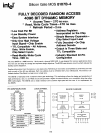

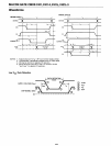
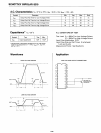
SILICON GATE MOS
81078·4
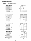
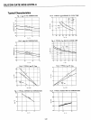
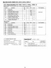
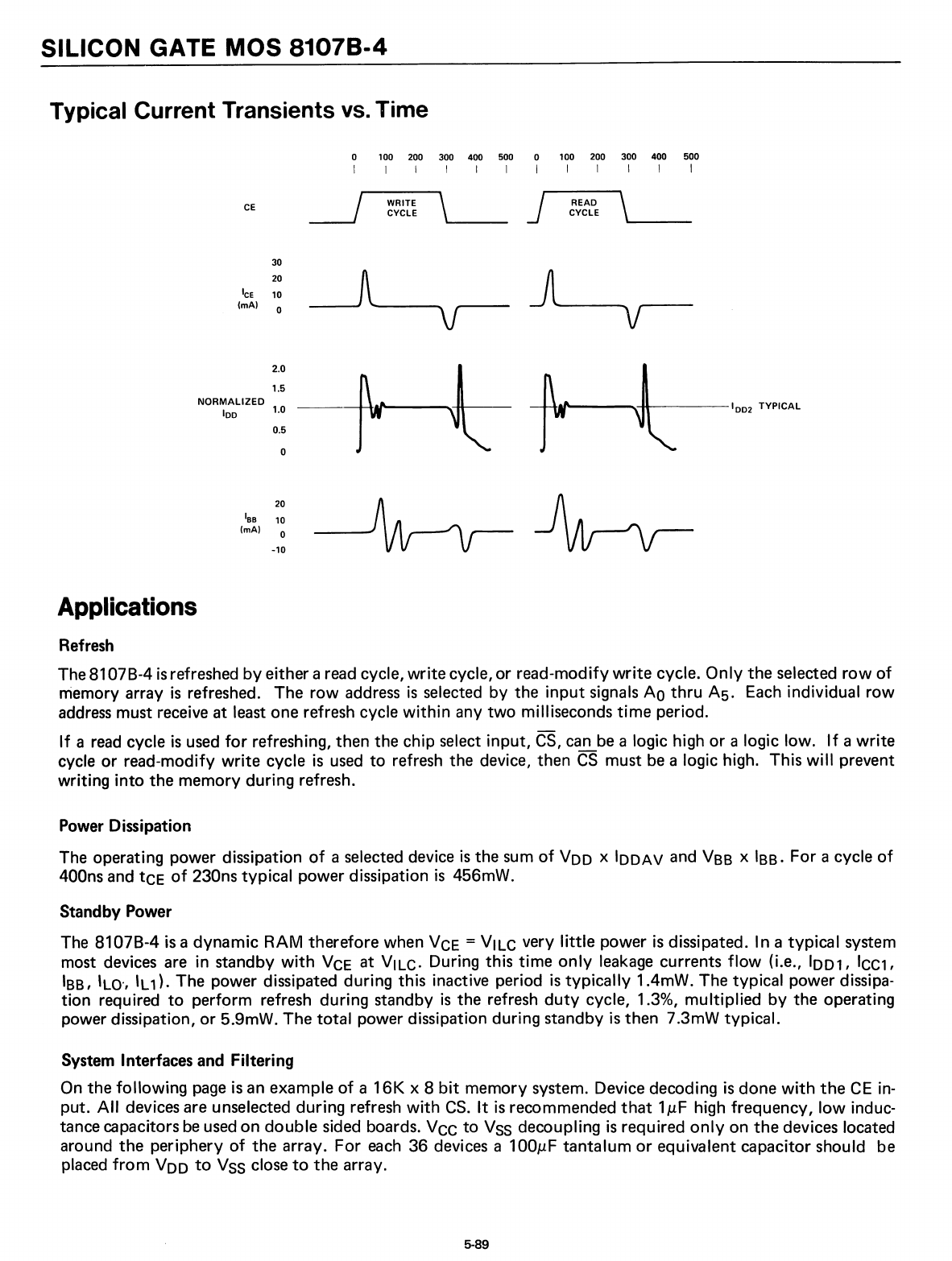
Typical Current Transients
Ys.
Time
100 200
300
400
500
0
100
200
300
400
500
I
I I I
I
I
I
I I
I
I
CE
~
WRITE
\
J
READ
\
CYCLE CYCLE
30
20
A
J
Ice
10
(rnA)
0
V
V
2.0
1.5
NORMALIZED
100
1.0
0.5
a
20
Iss
10
(rnA)
0
-10
--f-
....
AP---....~~----IDo2
TYPICAL
Applications
Refresh
The 81078-4
is
refreshed
by
either a
read
cycle,
write
cycle, or read-modify
write
cycle.
Only
the selected
row
of
niemory array
is
refreshed. The
row
address
is
selected by the
input
signals
AO
thru
A5.
Each
individual
row
address
must receive at least one refresh cycle
within
any
two
milliseconds
time
period.
If
a
read
cycle
is
used
for
refreshing, then the chip select input,
CS,
can
be
a logic high
or
a logic low.
If
a write
cycle or read-modify
write
cycle
is
used
to
refresh the device, then
CS
must
be
a logic high. This
will
prevent
writing
into
the memory during refresh.
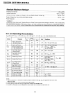
Power Dissipation
The operating power dissipation
of
a selected device
is
the
sum
of
Voo
x
100AV
and
Vss
x
Iss.
For a cycle
of
400ns
and
tCE
of
230ns typical power dissipation
is
456mW.
Standby
Power
The 81078-4
is
a dynamic RAM therefore when
VCE
= VILC very
little
power
is
dissipated. In a typical system
most devices
are
in standby
with
VCE
at VILC. During this time
only
leakage
currents
flow
(Le.,
1001,
ICC1,
Iss,
'LO',
'L
1). The power dissipated during this inactive period
is
typically
1.4mW. The typical power dissipa-
tion required
to
perform refresh during standby
is
the refresh
duty
cycle, 1.3%, multiplied
by
the operating
power dissipation, or 5.9mW. The total power dissipation during standby
is
then 7.3mW typical.
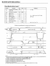
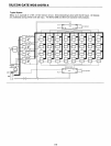
System Interfaces and Filtering
On the
following
page
is
an
example
of
a
16K
x 8
bit
memory system. Device decoding
is
done
with
the
CE
in-
put.
All
devices are unselected during refresh
with
CS.
It
is
recommended
that
1JJ.F
high frequency,
low
induc-
tance capacitors
be
used
on double sided boards.
VCC
to
VSS
decoupling
is
required
only
on
the
devices located
around the periphery
of
the array. For
each
36 devices a
100JJ.F
tantalum
or
equivalent capacitor should be
placed
from
VOO
to
VSS
close
to
the array.
5-89