


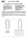
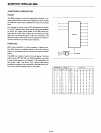
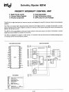
SCHOTTKY BIPOLAR 8205
Logic Element Example
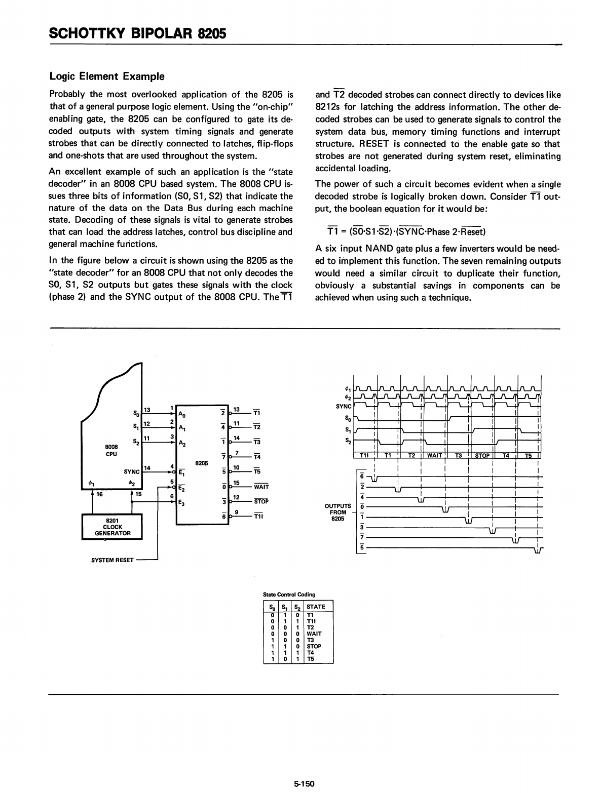
Probably
the
most
overlooked application
of
the
8205
is
that
of
a general purpose logic element. Using
the
lion-chip"
enabl
ing
gate,
the
8205
can be configured
to
gate its de-
coded
outputs
with system timing signals and generate
strobes
that
can be directly connected
to
latches, flip-flops
and one-shots
that
are used
throughout
the
system.
An excellent example
of
such an application
is
the
"state
decoder"
in
an
8008
CPU
based system.
The
8008
CPU
is-
sues three bits
of
information
(SO,
S1, S2)
that
indicate
the
nature
of
the
data
on
the
Data Bus during each machine
state. Decoding
of
these signals
is
vital
to
generate strobes
that
can load
the
address latches, control bus discipline and
general machine functions.
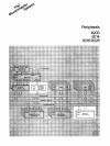
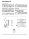
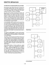
In
the
figure below a circuit
is
shown using
the
8205
as
the
"state
decoder"
for
an
8008
CPU
that
not
only decodes
the
SO,
51,
52
outputs
but
gates these signals
with
the
clock
(phase
2)
and
the
SYNC
output
of
the
8008
CPU.
The
T1
and
T2
decoded strobes can
connect
directly
to
devices like
8212s for latching
the
address information.
The
other
de-
coded strobes can be used
to
generate signals
to
control
the
system
data
bus, memory timing functions and interrupt
structure. RESET
is
connected
to
the
enable gate so
that
strobes are
not
generated during system reset, eliminating
accidental loading.
The
power
of
such a circuit becomes evident when a single
decoded strobe
is
logically broken down. Consider
T1
out-
put,
the
boolean equation
for
it would be:
Tl
= (SO·S1·S2)"(SYNC·Phase 2·Reset)
A six
input
NAND gate plus a few inverters would
be
need-
ed
to
implement
this function.
The
seven remaining
outputs
would need a similar circuit
to
duplicate
their
function,
obviously a substantial savings
in
components
can be
achieved when using such a technique.
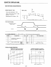
STOPT3
I
I-----i+----+-I
I
'----++-------tM---~1
I I I I
I I I I 1 I
6
\lJ I I I I I I
- I 1 I
2~
I I I i I
4"
----.....,~r----+I---+I--t-I
-""'"""I""'"--It-
o I
ro----++-----:I--+---..-I
------~\lJ
I I I
l------------,.wr----+\--:....1
---+-1
3"
---------------,JJ,.--+-I
----.....1
7----------------,1
I
5
w--r
'ill
OUTPUTS
FROM
8205
820~
3
2
S 13
o
S
12
,
S
11
2
8008
CPU
SYSTEM RESET
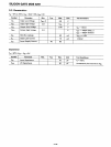
StateControl Coding
So
S,
S2
STATE
0
1
0
T1
0
1 1
T11
0
a
1
T2
a
0 0
WAIT
1
0 0 T3
1
1
0 STOP
1
1 1
T4
1
0 1
T5
5-150