


HOLD SEQUENCES
The
SOSOA
CPU
contains
provisions
for
Direct
Mem-
ory
Access (DMA)
operations.
By
applying
a HO
LD
to
the
appropriate
control
pin
on
the
processor,
an
external
device
can cause
the
CPU
to
suspend its
normal
operations
and
re-
linquish
control
of
the
address
and
data
busses.
The
proces-
sor
responds
to
a
request
of
this
kind
by
floating
its
address
to
other
devices sharing
the
busses.
At
the
same
time,
the
processor
acknowledges
the
HO
LD
by
placing a high
on
its
HLDA
outpin
pin. During
an
acknowledged
HOLD,
the
address
and
data
busses
are
under
control
of
the
peripheral
which originated
the
request,
enabling
it
to
conduct
mem-
ory
transfers
without
processor
intervention.
Like
the
interrupt,
the
HO
LD
input
is
synchronized
internally. A HOLD signal
must
be
stable
prior
to
the
"Hold
set-up"
interval (tHS),
that
precedes
the
rising edge
of
<P2.
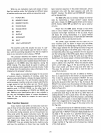
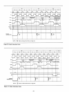
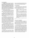
Figures 2-9
and
2-10
illustrate
the
timing
involved
in
HOLD operations.
Note
the
delay
between
the
asynchronous
HOLD REQUEST
and
the
re-clocked
HOLD.
As
shown
in
the
diagram, a
coincidence
of
the
READY,
the
HOLD,
and
the
¢2
clocks sets
the
internal
hold
latch.
Setting
the
latch
enables
the
subsequent
rising edge
of
the
¢1
clock
pulse
to
trigger
the
HLOA
output.
Acknowledgement
of
the
HOLD
REQUEST
precedes
slightly
the
actual floating
of
the
processor's
address
and
data lines.
The
processor
acknowledges
a HO
LD
at
the
begin-
ning
of
T3,
if
a read
or
an
input
machine
cycle
is
in
progress
(see Figure 2-9).
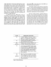
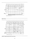
Otherwise,
acknowledgement
is
deferred
until
the
beginning
of
the
state
following
T3
(see Figure
2-10).
In
both
cases, however,
the
HLDA
goes high
within
a specified
delay
(tDC)
of
the
rising edge
of
the
selected ¢1
clock pulse. Address
and
data
lines are
floated
within
a
brief
delay
after
the
rising edge
of
the
next
¢2
clock
pulse.
This
relationship
is
also
shown
in
the
diagrams.
To
all
outward
appearances,
the
processor
has
suspend-
ed its
operations
once
the
address
and
data
busses
are
floated.
Internally, however,
certain
functions
may
continue.
If
a
HOLD
REQUEST
is
acknowledged
at
T3,
and
if
the
pro-
cessor
is
in
the
middle
of
a
machine
cycle
which
requires
four
or
more
states
to
complete,
the
CPU
proceeds
through
T4
and
T5
before
coming
to
a rest.
Not
until
the
end
of
the
machine cycle
is
reached will processing activities cease.
Internal processing
is
thus
permitted
to
overlap
the
external
DMA
transfer,
improving
both
the
efficiency
and
the
speed
of
the
entire
system.
The
processor
exits
the
holding
state
through
a
sequence
similar
to
that
by
which
it
entered.
A HOLD
REQUEST
is
terminated
asynchronously
when
the
external
device has
completed
its
data
transfer.
The
HLOA
output
returns
to
a
low
level following
the
leading edge
of
the
next
¢1
clock
pulse. Normal processing resumes
with
the
ma-
chine
cycle following
the
last
cycle
that
was
executed.
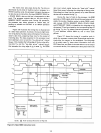
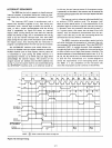
HALT
SEQUENCES
When a
halt
instruction
(H
L
T)
is
executed,
the
CPU
enters
the
haIt
state
(TWH)
after
state
T2
of
the
next
ma-
chine
cycle, as
shown
in
Figure 2-11.
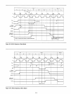
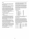
There
are
only
three
ways
in
which
the
8080
can
exit
the
halt
state:
• A high
on
the
RESET
line will
always
reset
the
8080
to
state
T 1;
RESET
also clears
the
program
counter.
• A HOLD
input
will cause
the
8080
to
enter
the
hold
state,
as previously
described.
When
the
HOLD line goes low,
the
8080
re-enters
the
halt
state
on
the
rising edge
of
the
next
¢1 clock
pulse.
•
An
interrupt
(Le., INT goes high
while
INTE
is
enabled) will cause
the
8080
to
exit
the
Halt
state
and
enter
state
T 1
on
the
rising edge
of
the
next
¢1
clock
pulse. NOTE:
The
interrupt
enable
(INTE)
flag
must
be
set
when
the
halt
state
is
entered;
otherwise,
the
8080
will
only
be
able
to
exit
via a
RESET
signal.
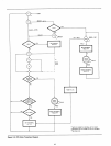
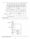
Figure
2-12
illustrates
halt
sequencing in
flow
chart
form.
START-UP OF THE 8080
CPU
When
power
is
applied
initially
to
the
8080,
the
pro-
cessor begins
operating
immediately.
The
contents
of
its
program
counter,
stack
pointer,
and
the
other
working
regis-
ters
are
naturally
subject
to
random
factors
and
cannot
be
specified.
For
this
reason,
it will be necessary
to
begin
the
power-up
sequence
with
RESET.
An
external
RESET
signal
of
three
clock
period
dura-
tion
(minimum)
restores
the
processor's
internal
program
counter
to
zero.
Program
execution
thus
begins
with
mem-
ory
location zero, following a RESET.
Systems
which
re-
quire
the
processor
to
wait
for
an
explicit
start-up
signal
will
store
a
halt
instruction
(EI, HLT) in
the
first
two
loca-
tions.
A manual
or
an
automatic
INTERRUPT
will
be
used
for
starting.
In
other
systems,
the
processor
may
begin ex-
ecuting
its
stored
program
immediately.
Note,
however,
that
the
RESET
has
no
effect
on
status
flags,
or
on
any
of
the
processor's
working
registers
(accumulator,
registers,
or
stack
pointer).
The
contents
of
these
registers
remain
inde-
terminate,
until initialized
explicitly
by
the
program.
2-13