


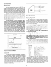

accumulator
Register A
addr
16-bit
address
quantity
data
8-bit
data
quantity
Symbols and Abbreviations:
The
following
symbols
and
abbreviations
are used in
the
subsequent
description
of
the
8080
instructions:
SYMBOLS MEANING
Auxiliary
Carry:
If
the
instruction
caused
a
carry
out
of
bit
3
and
into
bit
4
of
the
resulting
value,
the
auxiliary
carry
is
set;
otherwise
it
is
reset.
This
flag
is
affected
by
single
precision
additions,
subtractions,
incre-
ments,
decrements,
comparisons,
and
log-
ical
operations,
but
is
principally used
with
additions
and
increments
preceding
a DAA (Decimal
Adjust
Accumulator)
instruction.
Logical
AND
Exclusive 0 R
Inclusive
OR
Addition
Two's
complement
subtraction
Multiplication
"Is
exchanged
with"
The
one's
complement
(e.g., (A))
The
restart
number
a
through
7
The
binary
representation
000
through
111
for
restart
number
0
through
7 respectively.
"1
s
transferred
to"
n
NNN
*
( )
/\
V
V
+
rh
The
first
(high-order) register
of
a
designated
register pair.
rl
The
second
(low-order) register
of
a desig-
nated
register pair.
PC
16-bit
program
counter
register (PCH
and
PCl
are
used
to
refer
to
the
high-order
and
low-order 8
bits
respectively).
SP
16-bit
stack
pointer
register (SPH
and
SPL
are
used
to
refer
to
the
high-order
and
low-
order
8 bits respectively).
rm
Bit
m
of
the
register r (bits
are
number
7
through
a
from
left
to
right).
Z,S,P,CY,AC
The
condition
flags:
Zero,
Sign,
Parity,
Carry,
and
Auxiliary
Carry,
respectively.
The
contents
of
the
memory
location
or
reg-
isters
enclosed
in
the
parentheses.
DOD
or
SSS
REGISTER NAME
111 A
000
B
001 C
010
D
all
E
100
H
101 L
16-bit
data
quantity
The
second
byte
of
the
instruction
The
third
byte
of
the
instruction
8-bit
address
of
an
I/O device
One
of
the
registers
A,B,C,D,E,H,L
The
bit
pattern
designating
one
of
the
regis-
ters
A,B,C,D,E,H,L
(DDD=destination,
SSS=
source):
data
16
byte
2
byte
3
port
r,rl,r2
DDD,SSS
One
of
the
register pairs:
B represents
the
B,C pair
with
B as
the
high-
order
register
and
C as
the
low-order register;
D
represents
the
D,E pair
with
D as
the
high-
order
register
and
E as
the
low-order
register;
H represents
the
H,L pair
with
H as
the
high-
order
register
and
L
as
the
low-order register;
SP
represents
the
16-bit
stack
pointer
register.
The
bit
pattern
designating
one
of
the
regis-
ter
pairs B,D,H,SP:
rp
RP
RP
00
01
10
11
REGISTER PAIR
B-C
D-E
H-L
SP
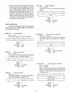
Description
Format:
The
following pages provide a
detailed
description
of
the
instruction
set
of
the
8080.
Each
instruction
is
de-
scribed in
the
following
manner:
1.
The
MAC
80
assembler
format,
consisting
of
the
instruction
mnemonic
and
operand
fields,
is
printed
in BOLDFACE
on
the
left
side
of
the
first
line.
2.
The
name
of
the
instruction
is
enclosed
in paren-
thesis
on
the
right
side
of
the
fi
rst
line.
3.
The
next
line(s)
contain
a
symbolic
description
of
the
operation
of
the
instruction.
4.
This
is
followed
by
a narative
description
of
the
operation
of
the
instruction.
5.
The
following line(s)
contain
the
binary
fields
and
patterns
that
comprise
the
machine
instruction.
4-3