


SILICON GATE MOS
8255
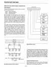
8255 DETAILED OPERATIONAL DESCRIPTION
Mode Selection
There
are
three
basic
modes
of
operation
that
can
be
select-
ed by
the
system
software:
Mode 0 - Basic
Input/Output
Mode 1 -
Strobed
Input/Output
Mode 2 - Bi-Directional Bus
When
the
RESET
input
goes
"high"
all
ports
will be
set
to
the
Input
mode
(Le., all 24 lines will be in
the
high im-
pedance
state).
After
the
RESET
is
removed
the
8255 can
remain
in
the
Input
mode
with
no
additional initialization
required. During
the
execution
of
the
system program
any
of
the
other
modes
may be selected using a single
OUTput
instruction.
This
allows a single 8255
to
service a variety
of
peripheral devices
with
a simple
software
maintenance
rou-
tine.
The
modes
for
Port
A
and
Port
B
can
be separately defined,
while
Port
C
is
divided
into
two
portions
as required by
the
PortA
and
Port
B definitions. All
of
the
output
registers,
in-
cluding
the
status
fl
ip-flops, will
be
reset whenever
the
mode
is
changed. Modes
may
be
combined
so
that
their
functional
definition
can
be
"tailored"
to
almost
any
I/O
structure.
For
instance;
Group
B can be programmed
in
Mode 0
to
monitor
simple switch closings
or
display
compu-
tational results,
Group
A
could
be
programmed in Mode 1
to
monitor
a
keyboard
or
tape
reader
on
an interrupt-driven
basis.
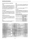
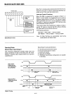
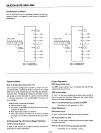
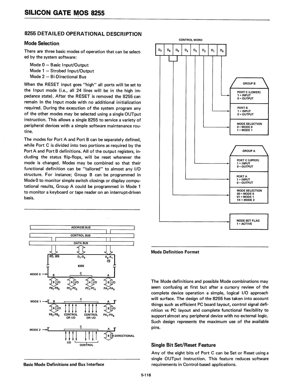
CONTROL WORD
~
GROUPB
'"
PORT C (LOWER)
~
1 = INPUT
0=
OUTPUT
PORTB
1 =INPUT
0=
OUTPUT
MODE SELECTION
0=
MODE 0
1 =MODE 1
;I'
GROUP
A
'"
PORT C (UPPER)
1 = INPUT
0=
OUTPUT
PORTA
1 =INPUT
0=
OUTPUT
MODE SELECTION
00=
MODE 0
01
= MODE 1
1X=MODE 2
MODE SET FLAG
1=ACTIVE
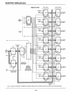
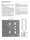
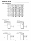
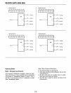
Basic Mode Definitions
and
Bus
Interface
C
MODE 1
--....rL.~~8~B
-1/-o..J;itllfTm=;;;;:;;:::;:t:=::::;:::;:;:::;;J.i-~~:~I.J/O
Pa,.PB
o
CONTROL CONTROL
PA
7
·pAo
OR
I/O
OR
I/O
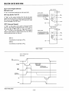
Single Bit Set/Reset Feature
Any
of
the
eight bits
of
Port
C can be
Set
or
Reset using a
single
OUTput
instruction.
This
feature
reduces software
requirements
in
Control-based applications.
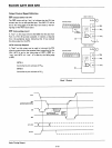
Mode Definition
Format
The
Mode
definitions
and possible Mode
combinations
may
seem confusing
at
first
but
after
a
cursory
review
of
the
complete
device
operation
a simple, logical I/O approach
will surface.
The
design
of
the
8255 has
taken
into
account
things such as efficient PC
board
layout,
control
signal defi-
nition
vs
PC
layout
and
complete
functional
flexibility
to
support
almost
any
peripheral device
with
no
external logic.
Such design represents
the
maximum
use
of
the
available
pins.
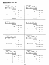
A r
~I.DIRECTIONAL
MODE 2
~"'----rrrnmi
I/O I
CONtROL
I
5-116