


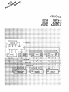

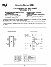

SCHOTTKY BIPOLAR 8224
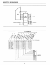
STSTB (Status Strobe)
At
the
beginning
of
each
machine
cycle
the
aOaOA CPU
is-
sues
status
information
on
its
data
bus.
Th
is
information
tells
what
type
of
action
will
take
place
during
that
machine
cycle. By bringing in
the
SYNC signal
from
the
CPU, and
gating it
with
an internal timing signal
(<1>1A),
an active low
strobe
can be derived
that
occu
rs
at
the
start
of
each ma-
chine cycle
at
the
earliest possible
moment
that
status
data
is
stable on
the
bus.
The
STSTB signal
connects
directly
to
the
8228
System
Controller.
The
power-on
R-eset
also generates STSTB,
but
of
course,
for
a longer
period
of
time.
This
feature
allows
the
8228
to
be
automatically
reset
without
additional
pins
devoted
for
th
is
fu nction.
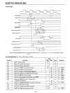
The
READY
input
to
the
8080A
CPU has
certain
timing
specifications such as
"set-up
and
hold"
thus,
an external
synchronizing flip-flop
is
required.
The
8224
has
this
feature
built-in.
The
ROYI N
input
presents
the
asynchronous
"wait
request"
to
the
"0"
type
flip-flop. By clocking
the
flip-flop
with
<1>20,
a
synchronized
READY
signal
at
the
correct
in-
put
level, can
be
connected
directly
to
the
a080A.
The
reason
for
requiring an
external
flip-flop
to
synchro-
nize
the
"wait
request"
rather
than
internally in
the
8080
CPU
is
that
due
to
the
relatively long delays
of
MOS logic
such an
implementation
would
"rob"
the
designer
of
about
200ns
during
the
time
his logic
is
determining
if a
"wait"
is
necessary. An
external
bipolar
circuit
built
into
the
clock
generator
eliminates
most
of
this
delay
and
has
no
effect
on
component
count.
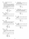
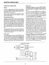
'9
12
5
"-----
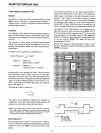
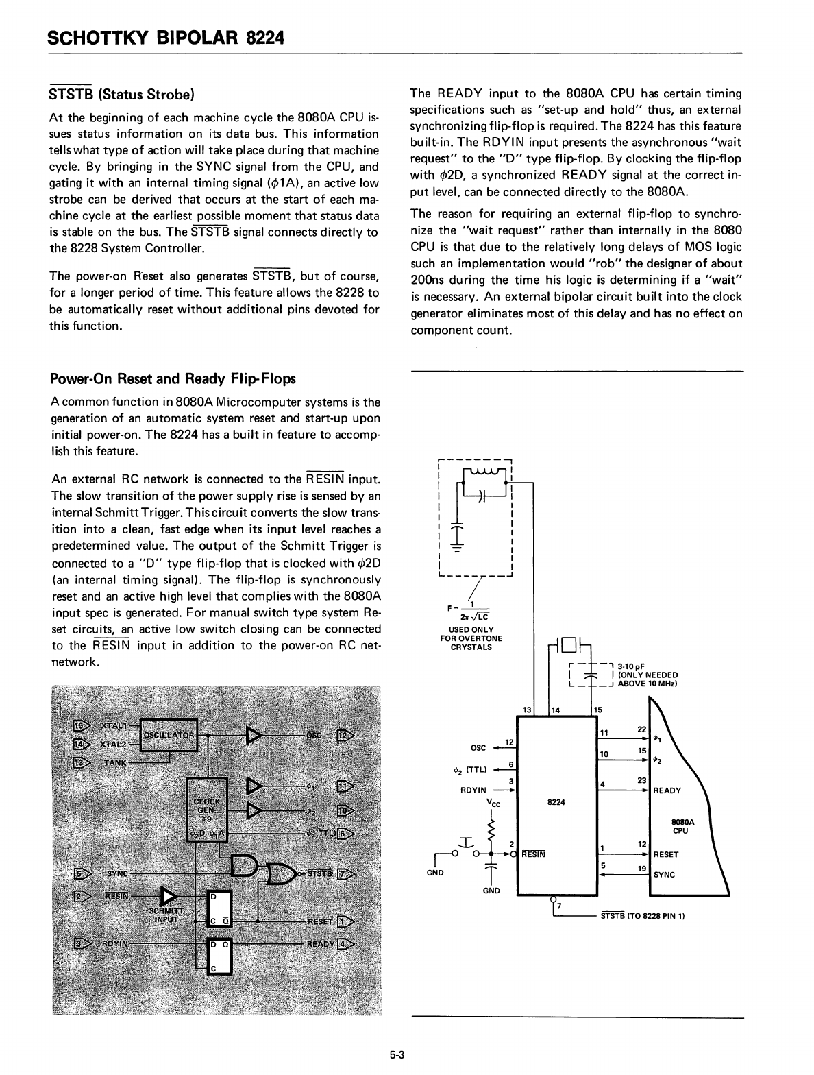
STSTB (TO 8228 PIN 1)
°1
r -
-,
3.10pF
I I (ONLV NEEDED
L_
_.J
ABOVE 10 MHz)
13
14
15
11
22
10
15
4
23
8224
6
3
12
T
GND
OSC
<fJ
2
(TTL)
GND
,------....,
1
I
I
I
1
:1
1-=
I
I
Ln7--
F=-'-
21rJLC
USEDONLV
FOR OVERTONE
CRYSTALS
An external RC
network
is
connected
to
the
R
ESI
N input.
The
slow
transition
of
the
power
supply
rise
is
sensed by an
internal
Schmitt
Trigger.
Thiscircuit
converts
the
slow trans-
ition into a clean, fast edge
when
its
input
level reaches a
predetermined value.
The
output
of
the
Schmitt
Trigger
is
connected
to
a
"0"
type
flip-flop
that
is
clocked
with
<1>20
(an internal timing signal).
The
flip-flop
is
synchronously
reset and an active high level
that
complies
with
the
aOaOA
input
spec
is
generated.
For
manual switch
type
system
Re-
set
circuits, an active low switch closing can be
connected
to
the
RESIN
input
in
addition
to
the
power-on
RC
net-
network.
Power-On Reset and Ready Flip-Flops
A
common
function
in
a080A
Microcomputer
systems
is
the
generation
of
an
automatic
system
reset
and
start-up
upon
initial power-on.
The
8224
has a
built
in
feature
to
accomp-
lish this feature.
5-3