


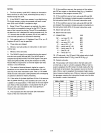

I/O INTERFACE
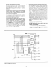
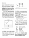
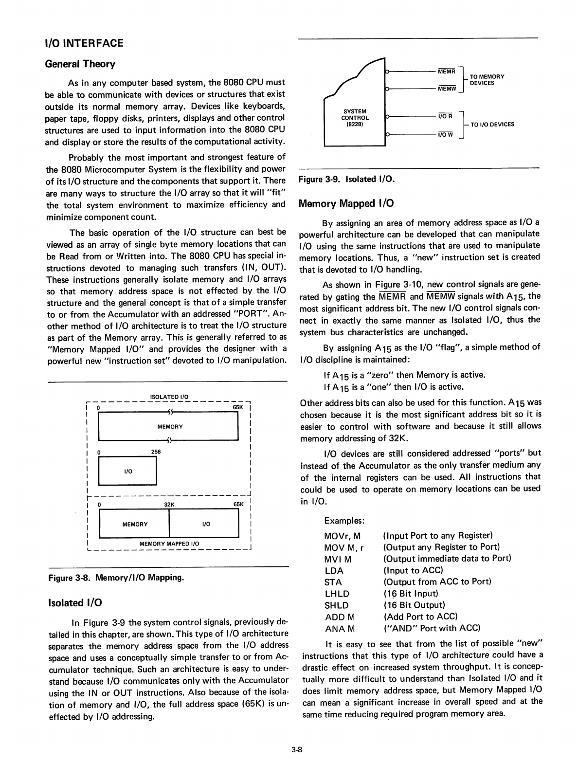
Figure 3-9. Isolated I/O.
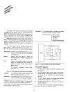
Memory Mapped
I/O
It
is
easy
to
see
that
from
the
list
of
possible
"new"
instructions
that
this
type
of
I/O architecture could have a
drastic
effect
on
increased system
throughput.
It
is
concep-
tually more difficult
to
understand
than
Isolated I/O and it
does limit
memory
address space,
but
Memory
Mapped I/O
can mean a significant increase
in
overall
speed
and
at
the
same
time
reducing
re~uired
program
memory
area.
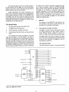
I/OR
}
TO
I/ODEVICES
~----I/OW
MEMR }
TO
MEMORY
__
DEVICES
~----MEMW
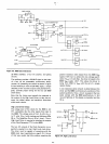
(I
nput
Port
to
any Register)
(Output
any Register
to
Port)
(Output
immediate
data
to
Port)
(I
nput
to
ACC)
(Output
from ACC
to
Port)
(1
~
Bit Input)
(16 Bit
Output)
(Add
Port
to
ACC)
("AND"
Port
with
ACC)
SYSTEM
CONTROL
(8228)
Examples:
MOVr, M
MOV
M,
r
MVI
M
LOA
STA
LHLO
SHLO
ADD M
ANAM
By assigning an area
of
memory
address space as I/O a
powerful architecture can be developed
that
can manipulate
I/O using
the
same instructions
that
are used
to
manipulate
memory locations.
Thus,
a
"new"
instruction
set
is
created
that
is
devoted
to
I/O handling.
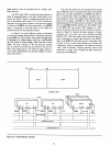
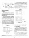
As
shown in Figure 3-10, new
control
signals are gene-
rated by gating
the
MEMR and
MEMW
signals
with
A15,
the
most significant address bit.
The
new I/O
control
signals con-
nect
in
exactly
the
same manner as Isolated I/O,
thus
the
system bus characteristics are unchanged.
By assigning
A15
as
the
I/O
"flag",
a simple
method
of
I/O discipline
is
maintained:
If
A15
is
a
"zero"
then
Memory is active.
If A15
is
a
"one"
then
I/O
is
active.
Other
address bits can also be used
for
this
function.
A15 was
chosen because it
is
the
most
significant address
bit
so
it
is
easier
to
control
with
software and because it still allows
memory addressing
of
32K.
I/O devices are still considered addressed
II
po
rts"
but
instead
of
the
Accumulator
as
the
only
transfer
medium any
of
the
internal registers can be used. All instructions
that
could be used
to
operate
on
memory
locations can be used
in
I/O.
General Theory
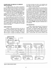
ISOLATED I/O
~--------------------I
1
ME;;RY
T!
o
~6
:
c:=J
i
I
r---------------------
j
! I
MEMORY
T
I/O
T!
I MEMORY
MAPPED
I/O I
~
J
Figure 3-8.
Memory/I/O
Mapping.
Isolated
I/O
In
Figure 3-9
the
system
control
signals, previously de-
tailed
in
this
chapter,
are shown.
Thi~
type
of
I/O architecture
separates
the
memory
address space from
the
I/O address
space and uses a conceptually simple transfer
to
or
from Ac-
cumulator
technique. Such an architecture
is
easy
to
under-
stand because I/O communicates
only
with
the
Accumulator
using
the
IN
or
OUT instructions. Also because
of
the
isola-
tion
of
memory
and I/O,
the
full address space (65K)
is
un-
effected
by
I/O addressing.
As in any
computer
based system,
the
8080
CPU must
be able
to
communicate
with
devices
or
structures
that
exist
outside its normal
memory
array. Devices like keyboards,
paper
tape,
floppy
disks, printers, displays and
other
control
structures
are used
to
'input
information
into
the
8080
CPU
and display
or
store
the
results
of
the
computational
activity.
Probably
the
most
important
and strongest feature
of
the
8080
Microcomputer System
is
the
flexibility and power
of
its I/O
structure
and
the
components
that
support
it. There
are
many
ways
to
structure
the
I/O array so
that
it will
"fit"
the
total
system environment
to
maximize efficiency and
minimize
component
count.
The
basic operation
of
the
I/O
structure
can best be
viewed as an array
of
single
byte
memory
locations
that
can
be Read from
or
Written into.
The
8080
CPU has special
in-
structions
devoted
to
managing such transfers (IN, OUT).
These instructions generally isolate
memory
and I/O arrays
so
that
memory
address space
is
not
effected by
the
I/O
structure and
the
general
concept
is
that
of
a simple transfer
to
or
from
the
Accumulator
with
an addressed
"PORT".
An-
other
method
of
I/O architecture
is
to
treat
the
I/O structure
as
part
of
the
Memory array. This
is
generally referred
to
as
"Memory Mapped
I/O"
and provides
the
designer with a
powerful new
"instruction
set"
devoted
to
I/O manipulation.
3-8