


APPLICATIONS EXAMPLE
The
8080
can be used as
the
basis
for
a wide variety
of
calculation and
control
systems.
The
system configura-
tions for particular applications will differ
in
the
nature
of
the
peripheral devices used
and
in
the
amount
and
the
type
of
memory
required.
The
applications
and
solutions de-
scribed
in
this
section are presented primarily
to
show
how
microcomputers
can be used
to
solve design problems.
The
8080
should
not
be considered limited
either
in
scope
or
performance
to
those
applications listed here.
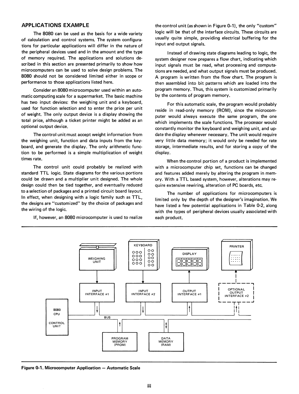
Consider an
8080
microcomputer
used
within
an auto-
matic
computing
scale
for
a
supermarket.
The
basic machine
has
two
input
devices:
the
weighing
unit
and
a
keyboard,
used for
function
selection
and
to
enter
the
price per
unit
of
weight.
The
only
output
device
is
a display showing
the
total price, although a
ticket
printer
might
be added as an
optional
output
device.
The
control
unit
must
accept
weight
information
from
the
weighing unit,
function
and
data
inputs
from
the
key-
board,
and
generate
the
display.
The
only
arithmetic
func-
tion
to
be performed
is
a simple
multiplication
of
weight
times rate.
The
control
unit
could
probably
be realized with
standard
TTL
logic.
State
diagrams
for
the
various
portions
could be
drawn
and
a multiplier
unit
designed.
The
whole
design could
then
be tied
together,
and
eventually reduced
to
a selection
of
packages
and
a
printed
circuit
board layout.
In
effect,
when
designing
with
a logic family such as
TTL,
the
designs are
"customized"
by
the
choice
of
packages
and
the
wiring
of
the
logic.
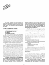
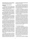
If, however, an
8080
microcomputer
is
used
to
realize
the
control
unit
(as
shown
in
Figure 0-1),
the
only
"custom"
logic will be
that
of
the
interface circuits. These circuits are
usually
quite
simple, providing electrical buffering
for
the
input
and
output
signals.
Instead
of
drawing
state
diagrams leading
to
logic,
the
system designer
now
prepares a flow
chart,
indicating which
input
signals
must
be read,
what
processing
and
computa-
tions
are needed, and
what
output
signa
Is
must
be
produced.
A program
is
written
from
the
flow
chart.
The
program
is
then
assembled
into
bit
patterns
which are loaded
into
the
program
memory.
Thus,
this
system
is
customized
primarily
by
the
contents
of
program
memory.
For
this
automatic
scale,
the
program
would
probably
reside
in
read-only
memory
(ROM), since
the
microcom-
puter
would
always
execute
the
same program,
the
one
which implements
the
scale functions.
The
processor
would
constantly
monitor
the
keyboard
and
weighing unit,
and
up-
date
the
display whenever necessary.
The
unit
would
require
very little
data
memory;
it
would
only
be needed
for
rate
storage,
intermediate
results,
and
for storing a
copy
of
the
display.
When
the
control
portion
of
a
product
is
implemented
with a
microcomputer
chip
set,
functions
can
be changed
and
features
added merely by altering
the
program
in
mem-
ory. With a
TTL
based
system,
however,
alterations
may
re-
quire extensive rewiring,
alteration
of
PC
boards, etc.
The
number
of
applications
for
microcomputers
is
limited
only
by
the
depth
of
the
designer's imagination.
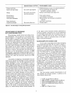
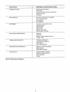
We
have listed a few
potential
applications
in
Table
0-2, along
with
the
types
of
peripheral devices usually associated
with
each
product.
,
I
I
I
-J
/
/
KEYBOARD
PRINTER
-
000
00
00
DISPLAY
000
CIJ
00
---
..
WEIGHING
000
1':II':II':~I':ff':'1
UNIT
00
000
00
I
II
II
II
II
I
1
1
T
+
I
I
r------
INPUT
INPUT
OUTPUT
I
OPTIONAL
I
OUTPUT
INTERFACE
#1
INTERFACE
#2
INTERFACE
#1
INTERFACE
#2
I
'---TT--
I+I
1+
It
I
ItI
8080
I I
CPU
I
L..--
BUS
CONTROL
It[
ItI
UNIT
PROGRAM
DATA
MEMORY
MEMORY
(PROM)
(RAM)
Figure 0-1. Microcomputer
Application
-
Automatic
Scale
iii