


SILICON GATE MOS 8255
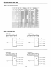
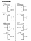
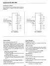
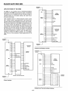
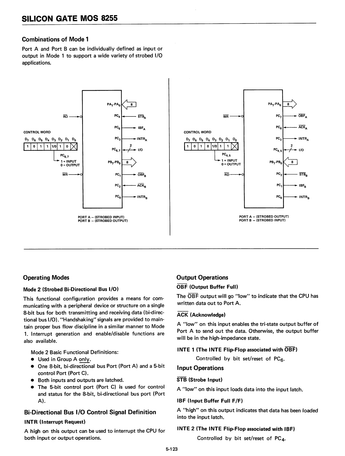
Combinations
of
Mode 1
Port A and
Port
B can be individually defined as input
or
output
in
Mode 1
to
support a wide variety
of
strobed I/O
applications.
PA
7
-PA
O
8
PC
7
OBF
A
PC
6
-+--
ACK
A
PC
3
INTRA
2
PC
4
•
5
I/O
PB
7
-PB
o
PC
2
STB
B
PC,
IBF
B
PC
o
INTR
B
CONTROL WORD
PC,
2
PC
6
•
7
..-.;-.-..
I/O
P~-PBO
8
PA
7
-PAo
8
PC
4
STB
A
PC
s
IBF
A
PC
3
INTRA
INTR
B
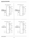
PORT A - (STROBED INPUT)
PORT B - (STROBED OUTPUT)
PORT A - (STROBED OUTPUT)
PORT B - (STROBED INPUT)
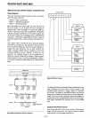
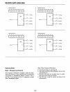
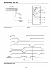
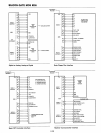
Operating Modes
Mode 2 (Strobed Bi-Directional
Bus
I/O)
This functional configuration provides a means for com-
municating with a peripheral device
or
structure on a single
8-bit bus for both transmitting and receiving
data
(bi-direc-
tional bus I/O). "Handshaking"signals are provided
to
main-
tain proper bus flow discipline
in
a similar manner
to
Mode
1.
Interrupt generation and enable/disable
fu
nctions are
also available.
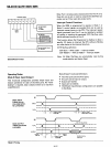
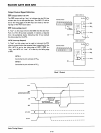
Output
Operations
OBF (Output
Buffer
Full)
The OBF
output
will go
"low"
to
indicate
that
the
CPU
has
written data
out
to
Port A.
ACK (Acknowledge)
A
"Iow"
on this input enables
the
tri-state
output
buffer
of
Port A
to
send
out
the
data. Otherwise, the
output
buffer
will be
in
the
high-impedance state.
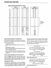
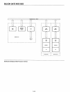
Mode 2 Basic Functional Definitions:
• Used in Group A only.
• One 8-bit, bi-directional bus Port (Port
A)
and a 5-bit
control Port (Port C).
• Both inputs and
outputs
are latched.
• The 5-bit control
port
(Port
C)
is
used for control
and status for
the
8-bit, bi-directional bus
port
(Port
A).
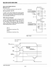
Bi-Directional
Bus
I/O
Control Signal
Definition
INTR
(Interrupt
Request)
A high on this
output
can be used
to
interrupt
the
CPU
for
both
input
or
output
operations.
INTE
1 (The
INTE
Flip-Flop
associated
with
OBF)
Controlled by
bit
set/reset
of
PCs.
Input
Operations
STB (Strobe
Input)
A
"low"
on
this
input
loads
data
into
the
input latch.
IBF
(Input
Buffer
Full
F/F)
A
"h
igh" on
th
is
output
indicates
that
data
has been loaded
into
the
input latch.
INTE
2 (The
INTE
Flip-Flop associated
with
IBF)
Controlled
by
bit set/reset
of
PC4.
5-123