


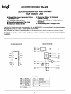

SCHOTTKY BIPOLAR
8224
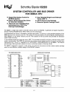
FUNCTIONAL DESCRIPTION
General
The
8224
is
a single
chip
Clock
Generator/Driver
for
the
S080A
CPU.
It
contains
a crystal-controlled oscillator, a
"divide
by
nine"
counter,
two
high-level drivers and several
auxiliary logic
functions.
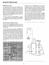
Oscillator
The
oscillator
circuit
derives its basic
operating
frequency
from an
external,
series
resonant,
fundamental
mode
crystal.
Two
inputs
are provided
for
the
crystal
connections
(XTAL1,
XTAL2).
The
selection
of
the
external crystal
frequency
depends
mainly
on
the
speed
at
which
the
8080A
is
to
be run at.
Basically,
the
oscillator
operates
at
9
times
the
desired pro-
cessor speed.
A simple
formula
to
guide
the
crystal selection is:
Crystal
Frequency
=
-'-
times
9
tCY
Example'
:
(500ns
tCY)
2mHz
times 9 =
18mHz*
Example
2:
(800ns
tCY)
'.25mHz
times
9 =
'1.25mHz
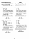
Another
input
to
the
oscillator
is
TANK.
This
input
allows
the
use
overtone
mode
crystals.
Th
is
type
of
crystal gen-
erally has
much
lower IIgain"
than
the
fundamental
type
so
an external
LC
network
is
necessary
to
provide
the
additional
"gain"
for
proper
oscillator
operation.
The
external
LC
net-
work
is
connected
to
the
TANK
input
and
is
AC
coupled
to
ground. See Figure
4.
The
formula
for
the
LC
network
is:
F=
__
l
__
21TVLC
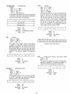
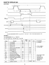
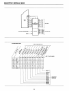
The
waveforms generated
by
the
decode
gating follow a
simple 2-5-2 digital
pattern.
See
Figure 2.
The
clocks
gen-
erated;
phase
1 and
phase
2,
can
best
be
thought
of
as con-
sisting
of
"units"
based
on
the
oscillator
frequency.
Assume
that
one
"unit"
equals
the
period
of
the
oscillator
frequency.
By multiplying
the
number
of
"units"
that
are
contained
in
a pulse
width
or
delay,
times
the
period
of
the
oscillator
fre-
quency,
the
approximate
time
in
nanoseconds
can
be
derived.
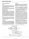
The
outputs
of
the
clock
generator
are
connected
to
two
high level drivers
for
direct
interface
to
the
80S0A
CPU. A
TTL
level phase 2
is
also
brought
out
ct>2
(TTL)
for
external
timing purposes.
It
is' especially useful in DMA
dependant
activities.
This
signal is used
to
gate
the
requesting device on-
to
the
bus
once
the
8080A
CPU issues
the
Hold Ack-
nowledgement
(H
LOA).
Several
other
signals are also generated
internally
so
that
optimum
timing
of
the
auxiliary flip-flops and
status
strobe
(STSTB)
is
achieved.
The
output
of
the
oscillator
is
buffered
and
brought
out
on ElSC (pin 12) so
that
other
system
timing
signals
can
be
derived
from
this stable, crystal-controlled source.
*When using crystals above
10mHz
a small
amount
of
frequency
"trimming"
may be necessary
to
produce
the
exact desired fre-
quency.
The
addition
of
a small selected capacitance (3pF -
10pF)
in series
with
the
crystal
will
accomplish
this
function.
4>,
1 UNIT=
o~c.
FREQ.
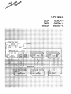
Clock Generator
The
Clock
Generator
consists
of
a
synchronous
IIdivide by
nine"
counter
and
the
associated
decode
gating
to
create
the
waveforms
of
the
two
8080A
clocks
and
auxiliary timing
signals.
5-2
EXAMPLE: (8080 t
CY
=500ns)
OSC
= 18mHz/55ns
4>1
= 110ns (2 x 55ns)
cP2
= 275ns (5 x 55ns)
4>2-4>,
=110ns (2 x 55ns)