


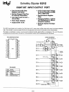
SCHOTTKY BIPOLAR
8212
8080 Status Latch
8008 System
8080 System:
8 Input Ports
8 Output Ports
8 Level Priority Interrupt
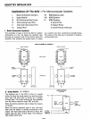
Applications
Of
The 8212 -- For Microcomputer Systems
I Basic Schematic Symbol VII
II
Gated Buffer VIII
III Bi-Directional Bus Driver
IX
IV Interrupting Input Port
V Interrupt Instruction Port
VI
Output Port
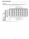
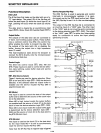
I.
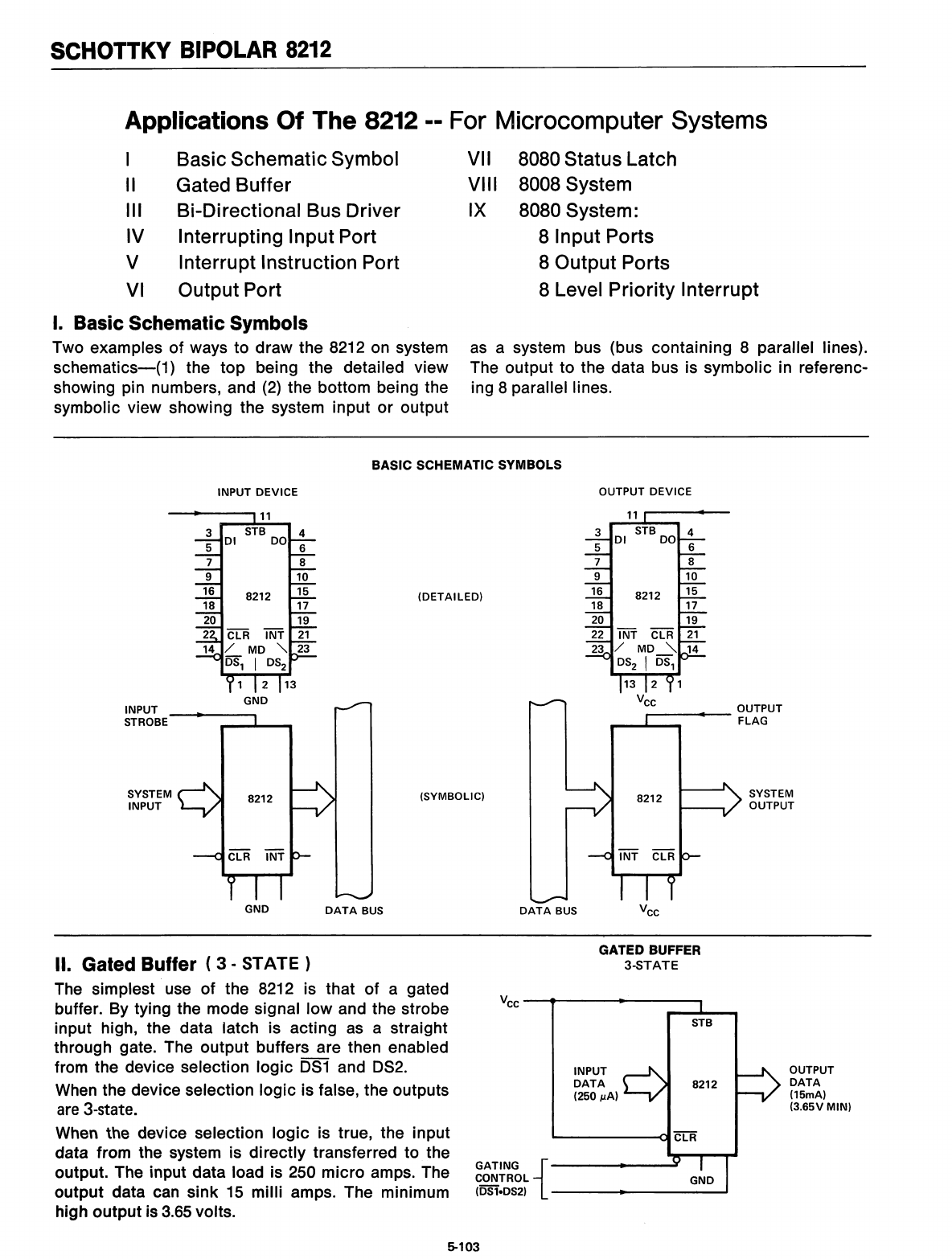
Basic Schematic Symbols
Two examples of ways to draw the 8212 on system
as
a system bus (bus containing 8 parallel lines).
schematics-(1)
the top being the detailed view The output to the data bus is symbolic in referenc-
showing pin numbers, and
(2)
the bottom being the ing 8 parallel lines.
symbolic view showing the system input or output
BASIC SCHEMATIC SYMBOLS
INPUT
DEVICE
OUTPUT
DEVICE
SYSTEM
OUTPUT
8212
INT
CLR
4
6
8
10
8212 15
17
19
-
--
INT
CLR
21
/ MD
'"
14
DS
2
I
~
13 2 1
Vee
_---....-
OUTPUT
FLAG
11~-~
3
01
STB DO
5
7
9
16
18
20
22
23
DATA
BUS
(SYMBOLIC)
(DETAILED)
DATA
BUS
8212
8212
CLR
INT
GND
3
5
01
7
9
16
18
20
SYSTEM
INPUT
INPUT
STROBE
8TB
"""'------C)I
CLR
OUTPUT
DATA
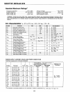
(15mA)
(3.65V MIN)
GATED BUFFER
3-STATE
INPUT
DATA
8212
(250
~A)
Vee
-------..----
GATING
{
CONTROL
(081-082)
---......--------'
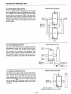
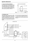
II. Gated Buffer (
3·
STATE)
The simplest use of the 8212 is that of a gated
buffer. By tying the mode signal low and the strobe
input high, the data latch is acting
as
a straight
through gate. The output buffers are then enabled
from the device selection logic 051 and 052.
When
the device selection logic is false, the outputs
are 3-state.
When the device selection logic is true, the input
data from the system is directly transferred to the
output. The input data load is 250 micro amps. The
output data can sink
15
milli amps. The minimum
high output is
3.65
volts.
5-103