


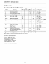
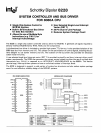
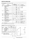
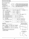
SCHOTTKY BIPOLAR 8228
D.C. Characteristics
TA
= O°c
to
70°C; Vee =
5V
±5%.
Limits
Symbol
Parameter
Min.
Typ.[1]
Max.
Unit
Test Conditions
Ve
Input
Clamp Voltage,
All
Inputs
.75
-1.0
V
Vee=4.75V;
le=-5mA
IF
Input
Load Current,
STSTB
500
IlA
Vee=5.25V
02&06
750
IlA
VF=O.45V
Do,
01, 04,
Os,
Il
A
&
07
250
All
Other Inputs
250
Il
A
IR
Input
Leakage
Current
STSTB
100
Il
A
Vee=5.25V
OBo-OB7
20
IlA
VR
=5.25V
All
Other Inputs
100
p.A
VTH
Input
Threshold Voltage,
AU
Inputs
0.8
2.0
V
VCC=5V
Icc
Power Supply Current
140
190
mA
VCC=5.25V
VOL
Output
Low Voltage,
00-
0
7
.45
V
VCC=4.75V;
IOl
=2mA
All
Other Outputs
.45
V
IOl
= 10mA
VOH
Output
High Voltage,
00-
0
7
3.6
3.8
V
VcC=4.75V; IOH=-10p.A
All
Other Outputs
2.4
V
IOH
=
-1mA
los
Short Circuit Current,
All
Outputs
15
90
mA
V
ec
=5V
10
(off)
Off
State
Output
Current,
All
Control Outputs
100
IlA
Vce=5.25V; VO=5.25
-100
p.A
VO=·45V
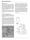
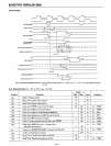
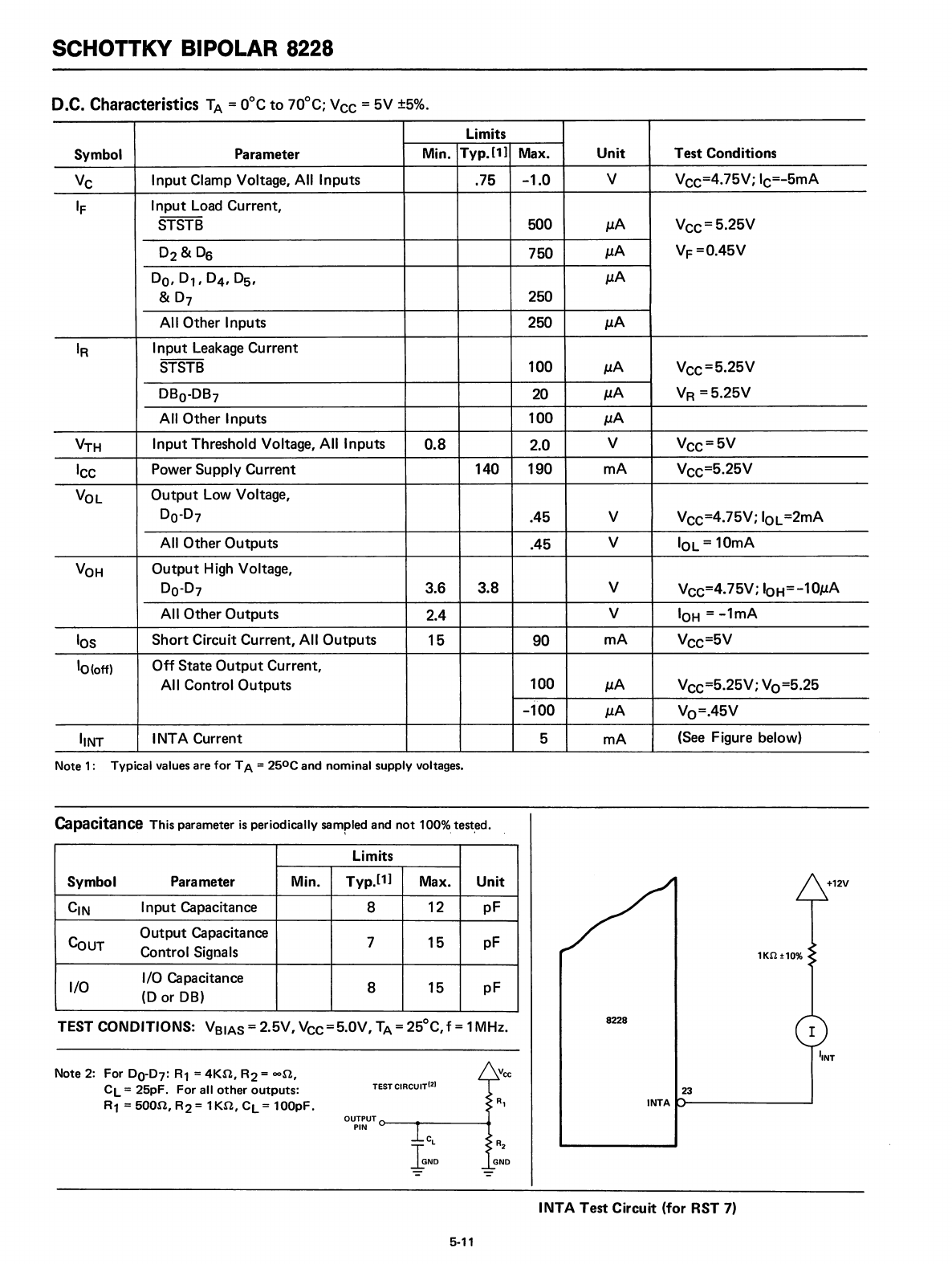
liNT
INTA Current
5
mA
(See
Figure below)
Note 1: Typical values are for TA = 2S
o
e and nominal supply voltages.
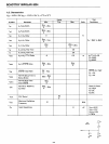
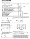
Capacitance This parameter
is
periodically sampled and
not
100%.
test,ed.
Limits
Symbol
Parameter
Min.
Typ.£1]
Max.
Unit
elN
Input
Capacitance
8
12
pF
GoUT
Output
Capacitance
7
15
pF
Control Signals
I/O
I/O Capacitance
8 15
pF
(0
or
OB)
TEST CONDITIONS:
VBIAS
= 2.5V, Vcc=S.OV,
TA
= 2Soe, f = 1MHz.
Note 2: For
00-07:
R1
=
4Kn,
R2
= oon,
cL
= 25pF. For all
other
outputs:
R1
=
500n,
R2=
1Kn,
CL
=
100pF.
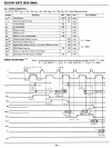
5-11
8228
23
INTA
INTA
Test Circuit
(for
RST
7)