


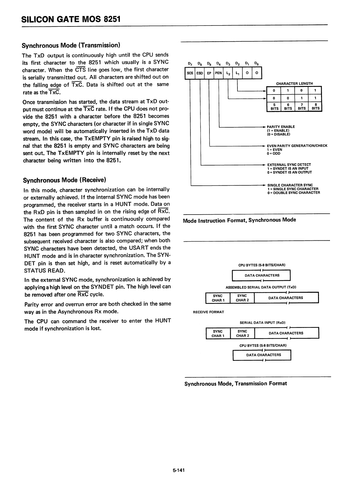
SILICON GATE MOS 8251
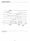
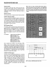
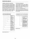
o 0 1 1
5 6 7 8
BITS BITS BITS BITS
L.....-
-..
PARITY ENABLE
(1
=ENABLE)
(0
= DISABLE)
1 0
CHARACTER LENGTH
o
L.....-
..
EVEN PARITYGENERATION/CHECK
1
c EVEN
0=000
Synchronous Mode (Transmission)
The TxD
output
is
continuously high until
the
CPU
sends
its first character
to
the
8251 which usually
is
a SYNC
character. When
the
CTS line goes low,
the
first character
is
serially transmitted out.
All
characters are shifted
out
on
the falling edge
of
TxC. Data
is
shifted
out
at
the
same
rate
as
the
TxC.
Once transmission has started,
the
data
stream
at
TxD out-
put
must continue
at
the
TxC rate. If
the
CPU
does
not
pro-
vide the 8251 with a character before
the
8251 becomes
empty, the SYNC characters (or character if
in
single SYNC
word mode) will be automatically inserted
in
the
TxD
data
stream.
In
this case,
the
TxEMPTY pin
is
raised high
to
sig-
nal
that
the
8251
is
empty
and SYNC characters are being
sent
out.
The
TxEMPTY pin
is
internally reset by
the
next
character bei
ng
written into
the
8251.
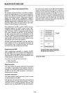
'"-----------..
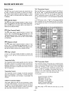
EXTERNAL
SYNC DETECT
1
=SYNDET
IS
AN INPUT
o= SYNDET
IS
AN OUTPUT
SERIAL
DATA
INPUT (RxD)
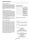
RECEIVE FORMAT
DATACHAR~~C_TE_R_S
___
CPU
BYTES (5-8 BITS/CHAR)
~
f
DATA
CH:~ACTERS
CPU
BYTES (5-8 BITS/CHAR)
DATA
C~~RACTERS
ASSEMBLED SERIAL
DATA
OUTPUT (TxD)
DATACHA~~AC_T_E_RS
~
"-------------
....
SINGLE CHARACTER SYNC
1
= SINGLE SYNC CHARACTER
0=
DOUBLE SYNC CHARACTER
Mode Instruction Format, Synchronous Mode
Synchronous Mode (Receive)
In
this mode, character synchronization can be internally
or externally achieved. If
the
internal SYNC mode has been
programmed,
the
receiver starts
in
a HUNT mode. Data on
the
Rx.D
pin
is
then sampled
in
on
the
rising edge of RxC.
The
content
of
the
Rx buffer
is
continuously compared
with
the
first SYNC character until a match occurs. If the
8251 has been programmed for two SYNC characters,
the
subsequent received character
is
also compared; when both
SYNC
characters have been detected,
the
USART ends
the
HUNT mode and
is
in character synchronization.
The
SYN-
DET
pin
is
then set high, and
is
reset automatically by a
STATUS READ.
In
the external SYNC mode, synchronization
is
achieved by
applying a high
level
on
the
SYNDET pin.
The
high level can
be removed after one RxC cycle.
Parity error and overrun error are
both
checked
in
the
same
way
as
in
the
Asynchronous Rx mode.
The
CPU
can command
the
receiver
to
enter
the
HUNT
mode if synchronization
is
lost.
Synchronous Mode, Transmission Format
5-141