


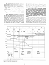
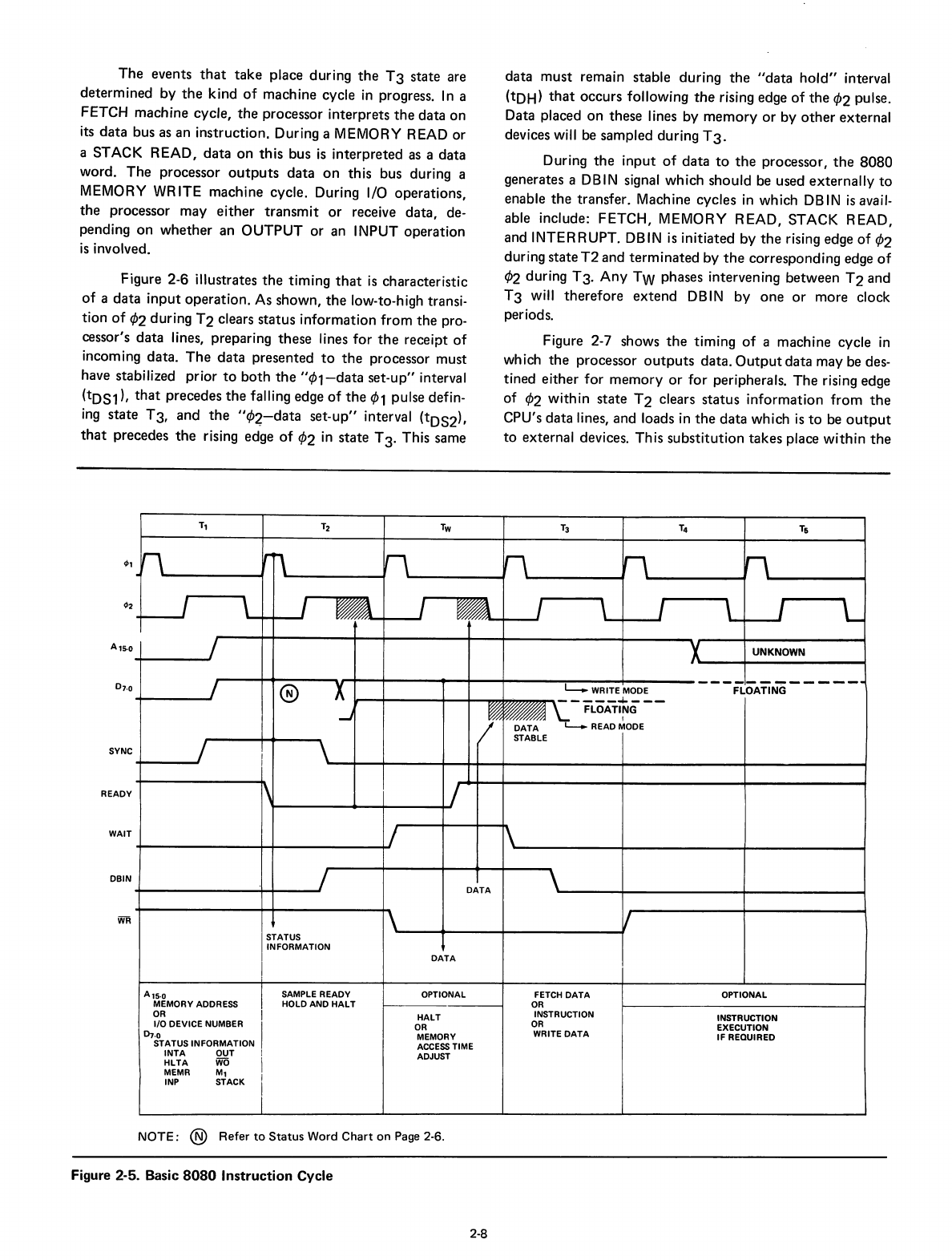
The
events
that
take
place
during
the
T3
state
are
determined
by
the
kind
of
machine
cycle
in
progress.
In
a
FETCH
machine
cycle,
the
processor
interprets
the
data
on
its
data
bus as an
instruction.
During a MEMORY READ
or
a STACK
READ,
data
on
this
bus
is
interpreted
as a
data
word.
The
processor
outputs
data
on
this
bus
during a
MEMORY WRITE
machine
cycle. During I/O
operations,
the
processor
may
either
transmit
or
receive
data,
de-
pending
on
whether
an
OUTPUT
or
an INPUT
operation
is
involved.
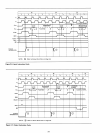
Figure 2-6 illustrates
the
timing
that
is
characteristic
of
a
data
input
operation.
As
shown,
the
low-to-high transi-
tion
of
<P2
during
T2
clears
status
information
from
the
pro-
cessor's
data
lines, preparing
these
lines
for
the
receipt
of
incoming
data.
The
data
presented
to
the
processor
must
have stabilized
prior
to
both
the
"¢1-data
set-up"
interval
(tDS1),
that
precedes
the
falling edge
of
the
¢1 pulse defin-
ing
state
T3,
and
the
"¢2-
data
set-up"
interval (tDS2),
that
precedes
the
rising edge
of
<P2
in
state
T
3.
This same
data
must
remain
stable
during
the
"data
hold"
interval
(tDH)
that
occurs
following
the
rising edge
of
the
<P2
pulse.
Data placed
on
these
Iines
by
memory
or
by
other
external
devices will be
sampled
during
T3.
During
the
input
of
data
to
the
processor,
the
8080
generates a DBIN signal
which
should
be used
externally
to
enable
the
transfer.
Machine
cycles
in
which
DB
IN
is
avail-
able include:
FETCH,
MEMORY
READ,
STACK
READ,
and
INTERRUPT.
DBIN
is
initiated
by
the
rising edge
of
¢2
during
state
T2
and
terminated
by
the
corresponding
edge
of
<P2
during
T3.
Any
TW phases intervening
between
T2
and
T3
will
therefore
extend
DBIN
by
one
or
more
clock
periods.
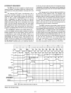
Figure 2-7 shows
the
timing
of
a
machine
cycle
in
which
the
processor
outputs
data.
Output
data
may
be des-
tined
either
for
memory
or
for
peripherals.
The
rising edge
of
<P2
within
state
T2
clears
status
information
from
the
CPU's
data
lines,
and
loads in
the
data
which
is
to
be
output
to
external
devices.
This
substitution
takes
place
within
the
4>1
A,S-O
SYNC
READY
WAIT
DBIN
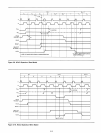
T1
T2
Tw
T3
T4
T6
n
rr\
n
n
rl
n
L.-J
,
f
,
f \
I
L
~
UNKNOWN
-----
-
---
_-..-
®
X
L..... WRITE MODE FLOATING
-----~---
--J
FLOATING
I
DATA
~READMODE
STABLE
I
\
\
DATA
V
STATUS
INFORMATION
DATA
A,S·0
SAMPLE READY
OPTIONAL
FETCH
DATA
OPTIONAL
MEMORY ADDRESS
HOLD AND
HALT
OR
OR
HALT
INSTRUCTION
INSTRUCTION
1/0
DEVICE NUMBER
OR
OR
EXECUTION
0-,,0
MEMORY
WRITE
DATA
IF
REQUIRED
STATUS INFORMATION
ACCESS
TIME
INTA
OUT
ADJUST
HLTA
WO
MEMR
M,
INP
STACK
NOTE;
®
Refer
to
Status
Word
Chart
on
Page 2-6.
Figure 2-5. Basic
8080
Instruction
Cycle
2-8