


SCHOTTKY BIPOLAR 8214
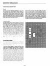
APPLICATIONS OF THE 8214
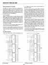
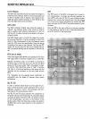
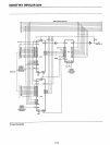
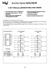
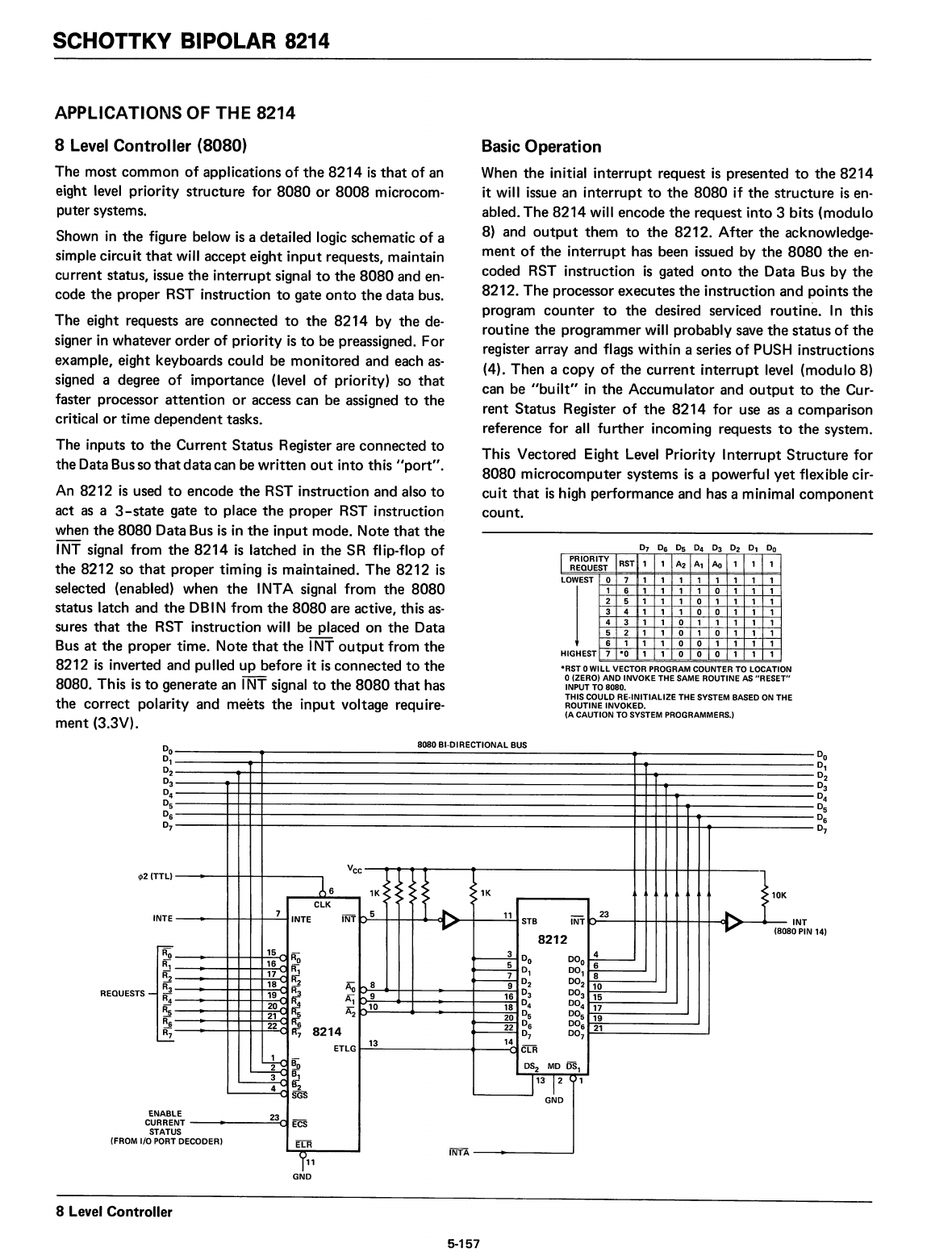
8 Level Controller (8080)
The most common
of
applications
of
the
8214
is
that
of an
eight
level
priority structure for
8080
or
8008
microcom-
puter systems.
Shown
in
the figure below
is
a detailed logic schematic
of
a
simple circuit
that
will accept eight
input
requests, maintain
current status, issue
the
interrupt signal
to
the
8080
and en-
code
the
proper RST instruction
to
gate
onto
the
data bus.
The eight requests are connected
to
the
8214
by the de-
signer
in
whatever order
of
priority
is
to
be preassigned. For
example, eight keyboards could be monitored and each
as-
signed a degree
of
importance (level
of
priority) so
that
faster processor attention
or
access can be assigned
to
the
critical
or
time dependent tasks.
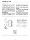
The inputs
to
the
Current Status Register are connected
to
the Data Busso
that
data
can be written
out
into this
"port".
An
8212
is
used
to
encode
the
RST instruction and also
to
act
as
a
3-state
gate
to
place
the
proper RST instruction
when
the
8080
Data Bus
is
in
the
input mode. Note
that
the
INT
signal from
the
8214
is
latched
in
the
SR flip-flop
of
the
8212 so
that
proper timing
is
maintained.
The
8212
is
selected (enabled) when
the
I
NT
A signal from
the
8080
status latch and
the
DB
IN from
the
8080
are active, this
as-
sures
that
the
RST instruction will be placed on
the
Data
Bus
at
the proper time. Note
that
the
I
NT
output
from
the
8212
is
inverted and pulled up before it
is
connected
to
the
8080. This
is
to
generate an INT signal
to
the
8080
that
has
the correct polarity and meets
the
input
voltage requ
ire-
ment
(3.3V).
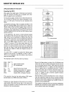
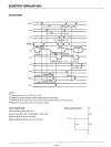
Basic
Operation
When
the
initial interrupt request
is
presented
to
the
8214
it will issue an interrupt
to
the
8080
if
the
structure
is
en-
abled. The
8214
will encode
the
request into 3 bits (modulo
8) and
output
them
to
the
8212. After the acknowledge-
ment
of
the
interrupt has been issued by
the
8080
the
en-
coded RST instruction
is
gated
onto
the
Data Bus by
the
8212. The processor executes
the
instruction and points the
program
counter
to
the
desired serviced routine.
In
this
routine
the
programmer will probably save
the
status
of
the
register array and flags within a series
of
PUSH instructions
(4). Then a
copy
of
the
current
interrupt level (modulo 8)
can be
"built"
in
the
Accumulator and
output
to
the Cur-
rent Status Register
of
the
8214
for use
as
a comparison
reference for
all
further
incoming requests
to
the
system.
This Vectored Eight
Level
Priority Interrupt Structure for
8080
microcomputer systems
is
a powerful
yet
flexible cir-
cuit
that
is
high performance and has a minimal
component
count.
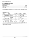
I PRIORITY
RST
1 1
A2
Al
Ao
1 1 1
REQUEST
LOWEST
0 7
1 1 1
1 1
1 1 1
1 6
1
1
1
1 0
1
1
1
2
5 1
1
1 0 1
1
1
1
3
4 1
1
1
0 0
1
1
1
4 3 1 1 0 1
1
1 1
1
5
2 1 1
0
1
0
1 1
1
6
1 1
1 0 0
1 1
1
1
HIGHEST
7
-0
1
1
0 0 0
1 1
1
-RST 0WILLVECTOR PROGRAM COUNTER
TO
LOCATION
o(ZERO) AND INVOKE THE
SAME
ROUTINE
AS
"RESET"
INPUT
TO
8080.
THIS COULD RE·INITlALIZE THE
SYSTEM
BASED
ON
THE
ROUTINE INVOKED.
(ACAUTION
TO
SYSTEM PROGRAMMERS.)
8080 BI-DIRECTIONAL
BUS
14)
Vee
A6
1K
>
<C
:
1K
>10K
ClK
>
7
INTE
INT
b
5
11
INT
....
23
STB
'J
INT
(8080 PIN
8212
15 _
~
~
Do
00
0
...!....-
'6~
Fr.;
~
0
1
0°1
6
17
~
~
8
18
:::
R2
AQ
",8
9
O
2
00
2
10
19
~
Ai
Ai
....
9
16
0
3
00
3
15
20~
R;
~10
18
0
4
0°4
17
21
....
R5
Ai
~
05
0°5
19
22
;::
R6
8214
~
0
6
0°6
21
R7
0
7
0°7
ETlG
13
11-
ClR
....
~
~
DS
2
MD OSl
3
....
S;
113 1
2
01
4~
B2
....
SGS
GND
E
23
....
NT
....
ECS
S
DECODER)
ElR
1~1
INTA
ENABl
CURRE
STATU
(FROM I/O
PORT
REQUESTS
INTE
rj>2
(TTL)
GND
8 Level Controller
5-157