


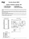
SCHOTTKY BIPOLAR
8214
APPLICATIONS OF
THE
8214
Cascading
the 8214
When greater
than
eight levels
of
interrupts
must
be priori-
tized and serviced,
the
8214
can
be
cascaded
with
other
8214s
to
support
such
an
.architecture.
On
the
previous page a simple circuit
is
shown
that
can con-
trol 16 levels
of
interrupt
and
is
easily
expandable
to
sup-
port
up
to
40
levels
of
interrupt
by just cascading more
8214s.
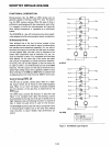
As described previously,
there
are signals provided
in
the
8214
for cascading (ELR, ETLG, ENLG) and in
effect
the
ENLG
output
of
the
first
8214
"ripples"
down
to
the
next
and so on.
The
entire
array
of
8214s
regardless
of
size, can
be
thought
of
as a single priority
control
unit,
with
the
first
having
the
highest priority and
the
next
8214
having a lower
priority and so
on.
In
this application,
the
manner
in which software handles
the
servicing
of
the
interrupt
will change. Since
more
than
eight vectors
must
be generated a
method
other
than
the
common RST instruction
must
be
implemented.
Basically,
the
priority control array
must
somehow
modify
the
con-
tents
of
the
8080
Program
Counter
so
that
it can
point
("vector")
to
one
of
16
(or
how
many
levels are
to
be
serviced) and fetch
the
proper
service routine. A simple ap-
proach
is
to
treat
the
priority
control
array as a single
input
port
that
can
input
a value
into
the
Accumulator
and use
this value as an
offset
to
modify
the
Program
Counter
(In-
direct
Jump).
An initial CALL
is
needed
to
invoke this Indirect
Jump
routine so
the
circuitry
is
configured
to
insert an RST 7
(FFh) for
all
interrupts,
thus
the
Indirect
Jump
Routine
starts
at
location (56d).
The
Assembly Code for
the
flow
chart
is
as follows:
RST7
SAVE
PROCESSOR
STATUS
INPUT
PRIORITY
ARRAY
VALUE
LOAD
BASE
VALUE
INTOH REGISTER
TRANSFER
H & L REGISTER
TO PROGRAM COUNTER
SERVICE ROUTINE
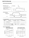
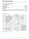
IREQUEST (PR)
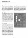
D-7
8-15
-
-
0 0
0
PRIORITIES
EN
EN
A2
A,
Ao
LOWEST
0
0
1 1 1 1 0 0 0
1
0 1
1 1
0
0 0
0
2 0 1
1
0 1 0 0
0
3 0 1 1 0 0
0 0
0
4
0
1 0 1
1
0 0
0
5
0 1
0 1
0
0
0
0
6
0
1 0
0
1 0 0 0
7 0 1
0
0
0 0 0
0
8 1
0 1 1
1
0
0 0
9 1 0 1 1 0 0 0
0
10
1
0
1
0
1
0
0 0
11
1
0
1 0 0 0 0 0
12
1
0 0 1
1
0
0
0
13
1
0 0 1 0 0 0 0
14 1
0
0
0
1
0
0 0
HIGHEST
15 1
0
0 0 0
0 0
0
(The execution
time
for
the
total
routine
is
35.5
micro-
seconds based
on
an
8080
clock period
of
500ns.)
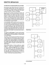
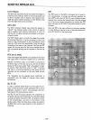
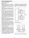
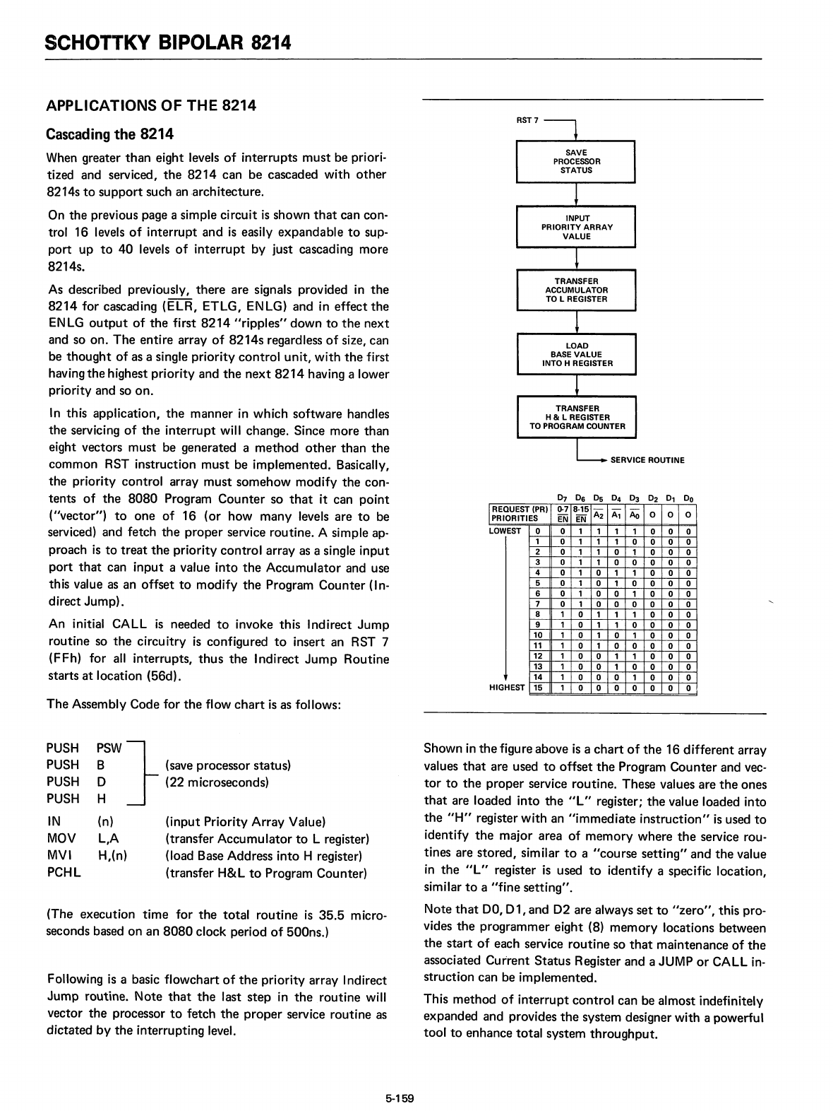
Following is a basic flowchart
of
the
priority array Indirect
Jump
routine.
Note
that
the
last
step
in
the
routine
will
vector
the
processor
to
fetch
the
proper
service routine as
dictated
by
the
interrupting level.
PUSH
PUSH
PUSH
PUSH
IN
MOV
MVI
PCHL
:SW}
(save processor status)
o (22 microseconds)
H
(n)
(input
Priority Array Value)
L,A (transfer
Accumulator
to
L register)
H,(n) (load Base Address
into
H register)
(transfer H&L
to
Program Counter)
Shown
in
the
figure above
is
a
chart
of
the
16
different
array
values
that
are used
to
offset
the
Program
Counter
and vec-
tor
to
the
proper
service routine. These values are
the
ones
that
are loaded
into
the
ilL" register;
the
value loaded into
the
"H"
register
with
an
"immediate
instruction"
is
used
to
identify
the
major area
of
memory
where
the
service rou-
tines are
stored,
similar
to
a
"course
setting"
and
the
value
in
the
ilL" register
is
used
to
identify
a specific location,
similar
to
a
"fine
setting".
Note
that
DO,
01,
and D2 are always
set
to
"zero",
this pro-
vides
the
programmer
eight
(8)
memory
locations between
the
start
of
each service
routine
so
that
maintenance
of
the
associated
Current
Status
Register and a JUMP
or
CALL
in-
struction can be
implemented.
This
method
of
interrupt
control
can be almost indefinitely
expanded and provides
the
system designer with a powerful
tool
to
enhance
total
system
throughput.
5-159