The
two (2) 8255s provide
twenty
four
bits each
of
programmable I/O
da~a
and control so
that
keyboards, sen-
sors, paper tape, etc., can be interfaced
to
the
system.
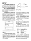
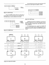
C/DCONTROL
_____________________ 8251SELECT
(ACTIVE
LOW)
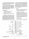
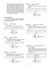
Figure 3-13. 8251 Format.
O-DATA
1-COMMAND
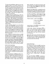
The three 8212s can be used
to
drive long lines
or
LED
indicators due
to
their high drive capability. (15mA)
________________________
8212
#1
SE
LECT
(ACTIVE HIGH)
___________
8212
#2
SELECT
(ACTIVE HIGH)
_____________
8212
#3
SELECT
(ACTIVE HIGH)
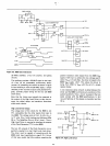
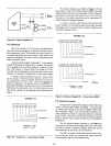
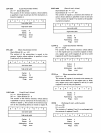
Figure 3-15. 8212 Format.
} PORT
SELECT
'---
8255
#1
SELECT
(ACTIVE
LOW)
"-------
8(~g::~~i~E~;r
OO-PORTA
01-PORTB
10
-PORTC
11-COMMAND
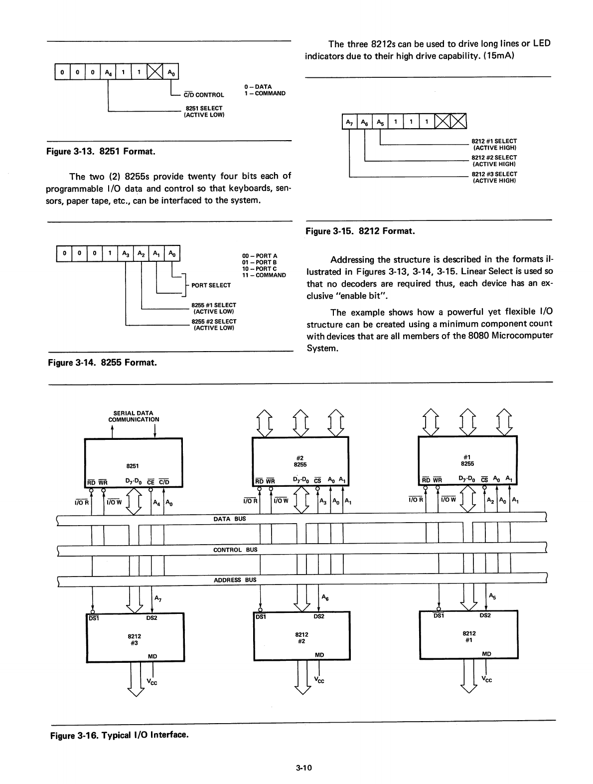
Addressing
the
structure
is
described
in
the
formats
il-
lustrated
in
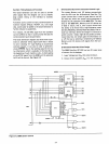
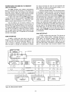
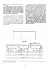
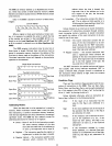
Figures 3-13, 3-14, 3-15. Linear Select
is
used so
that
no decoders are required thus, each device has an ex-
clusive "enable
bit".
The example shows how a powerful yet flexible I/O
structure can be created using a minimum
component
count
with devices
that
are
all
members
of
the
8080
Microcomputer
System.
Figure 3
..
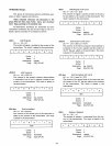
14. 8255 Format.
SERIAL DATA
COMMUNICATION
#1
8255
#2
8255
D~.Do
cs
Ao
A,
DATA
BUS
CONTROL
BUS
8251
8212
#3
8212
#2
8212
#1
MD
MD
MD
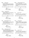
Figure 3-16. Typical
I/O
Interface.
3-10


