


SILICON GATE MOS
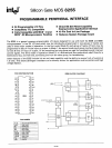
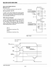
8255
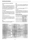
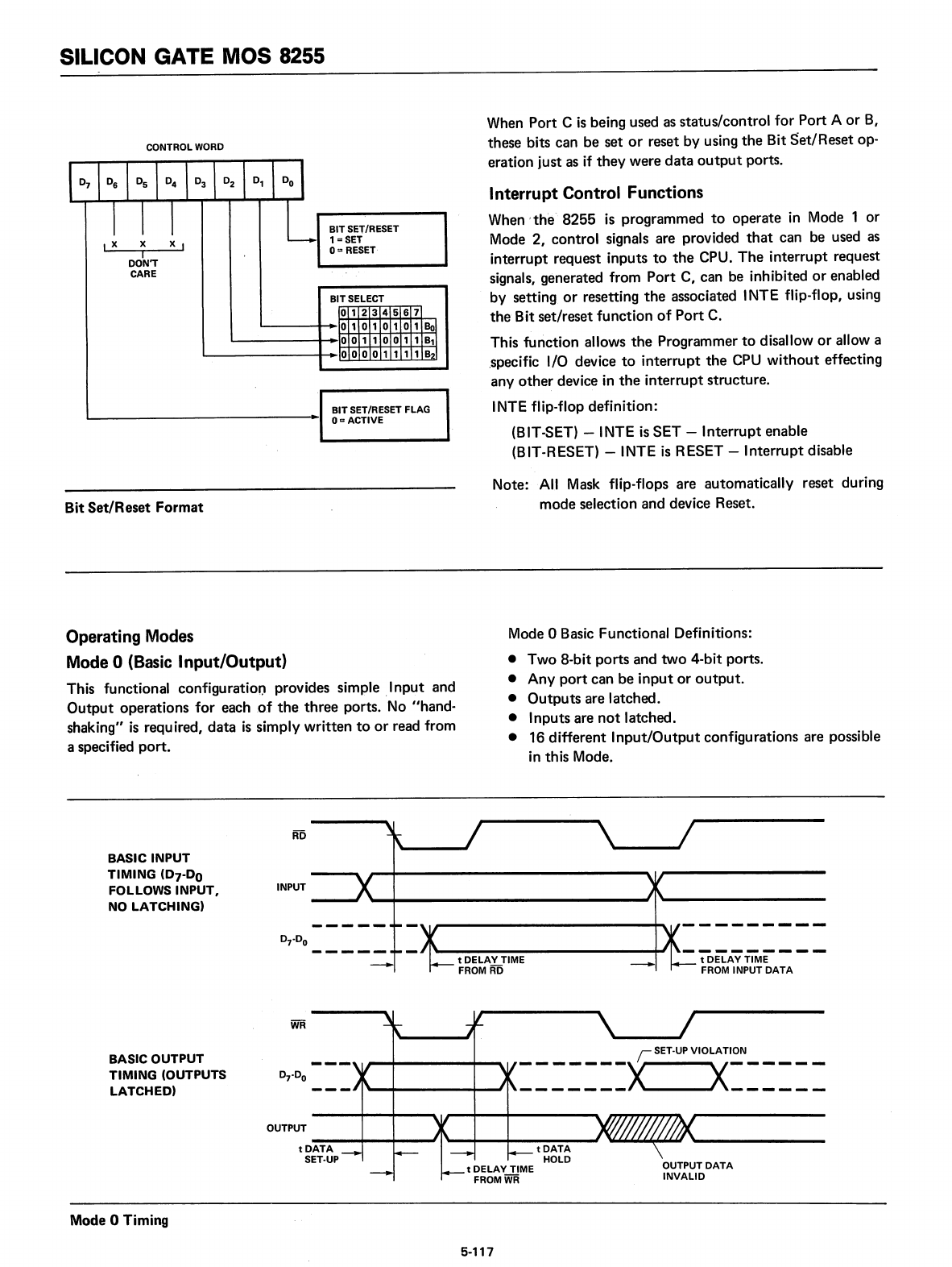
CONTROL
WORD
r0
7
t0
6
I
0
5
10
4
I
0
3
1O
2
I
0,
I
DO
I
I
I
I
L
BIT
SET/RESET
,x
X
x,
1=
SET
I
0::
RESET
DON'T
CARE
BITSELECT
o 1
2 3
4 5
6 7
o 1 o 1 o 1
o 1
801
o 0
1 1
o 0
1 1
B,-l
o 0 o 0
1 1
1 1
B21
BIT
SET/RESET FLAG
Om
ACTIVE
When Port C
is
being used as status/control
for
Port A
or
B,
these bits can be set
or
reset by using
the
Bit
Set/Reset
op-
eration just as if
they
were
data
output
ports.
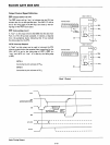
Interrupt
Control Functions
When'
the-'
8255
is
programmed
to
operate
in
Mode 1
or
Mode
2,
control signals are provided
that
can be used
as
interrupt request inputs
to
the
CPU.
The
interrupt
request
signals, generated from
Port
C, can be inhibited
or
enabled
by setting
or
resetting
the
associated INTE flip-flop, using
the' Bit set/reset function
of
Port
C.
This function allows
the
Programmer
to
disallow
or
allow a
.specific I/O device
to
interrupt
the
CPU
without
effecting
any
other
device
in
the
interrupt
structure.
INTE flip-flop definition:
(BIT-SET) - INTE
is
SET
-
Interrupt
enable
(BIT-RESET) - INTE
is
RESET -
Interrupt
disable
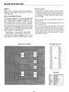
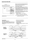
Bit
Set/Reset
Format
Note:
All
Mask flip-flops are automatically reset during
mode selection and device Reset.
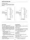
Operating Modes
Mode 0 (Basic
Input/Output)
This functional configuratioD provides simple
.1
nput
and
Output
operations for each
,of
the
three
ports. No "hand-
shaking"
is
required,
data
is
simply written
to
or
read from
a specified
port.
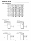
Mode 0 Basic Functional Definitions:
• Two 8-bit
ports
and
two
4-bit ports.
• Any
port
can
be
input
or
output.
•
Outputs
are latched.
• Inputs are
not
latched.
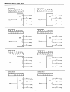
• 16 different
Input/Output
configurations are possible
in this Mode.
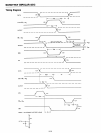
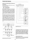
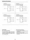
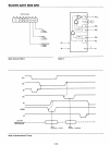
---------
t
DELAY
TIME
FROM INPUT
DATA
tDELAYTIME
FROM RD
BASIC
INPUT
TIMING
(07-00
FOLLOWS INPUT, INPUT
NO
LATCHING)
BASIC OUTPUT
TIMING
(OUTPUTS
LATCHED)
OUTPUT
tDATA
-.
SET·UP
~
SET·UP
VIOLATION
-------X
X------
-------
------
Mode 0 Timing
5-117