


INTERFACING THE 8080
CPU
TO MEMORY
AND I/O DEVICES
The
8080
interfaces
with
standard
semiconductor
Memory
components
and I/O devices.
In
the
previous
text
the
proper
control
signals
and
buffering were developed
which will
produce
a simple bus system similar
to
the
basic
system
example
shown
at
the
beginning
of
this
chapter.
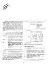
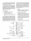
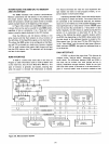
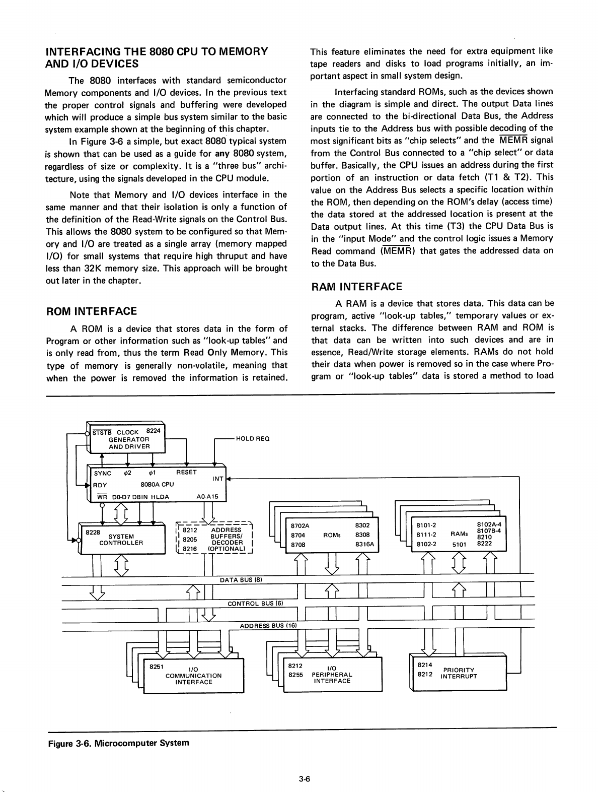
In
Figure
3-6
a simple,
but
exact
8080'
typical system
is
shown
that
can
be
used as a guide
for
any
8080
system,
regardless
of
size
or
complexity.
It
is
a
"three
bus"
archi-
tecture,
using
the
signals developed
in
the
CPU module.
Note
that
Memory and I/O devices interface
in
the
same manner and
that
their
isolation
is
only
a
function
of
the
definition
of
the
Read-Write signals
on
the
Control Bus.
This allows
the
8080
system
to
be configured so
that
Mem-
ory
and I/O are
treated
as a single array
(memory
mapped
I/O) for small systems
that
require high
thruput
and have
less
than
32K
memory
size. This
approach
will be
brought
out
later in
the
chapter.
This feature eliminates
the
need
for
extra
equipment
like
tape
readers and disks
to
load programs initially,
an
im-
portant
aspect in small system design.
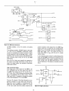
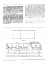
Interfacing
standard
ROMs, such as
the
devices
shown
in
the
diagram
is
simple
and
direct.
The
output
Data lines
are
connected
to
the
bi-directional Data Bus,
the
Address
inputs
tie
to
the
Address bus
with
possible decoding
of
the
most
significant bits as
II
c
hip
selects"
a~d
the
MEMR signal
from
the
Control Bus
connected
to
a
"chip
select"
or
data
buffer. Basically,
the
CPU issues an address during
the
first
portion
of
an instruction
or
data
fetch
(Tl
&
T2).
This
value
on
the
Address Bus selects a specific location within
the
ROM,
then
depending
on
the
ROM's delay (access time)
the
data
stored
at
the
addressed
location
is
present
at
the
Data
output
lines.
At
this
time
(T3)
the
CPU Data Bus
is
in
the
"input
Mode"
and
the
control
logic issues a Memory
Read
command
(MEMR)
that
gates
the
addressed
data
on
to
the
Data Bus.
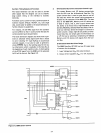
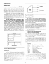
RAM INTERFACE
ROM
INTERFACE
A
ROM
is
a device
that
stores
data
in
the
form
of
Program
or
other
information
such as
"look-up
tables"
and
is
only
read
from,
thus
the
term
Read Only Memory. This
type
of
memory
is
generallY'non-volatile, meaning
that
when
the
power
is
removed
the
information
is
retained.
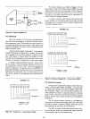
A
RAM
is
a device
that
stores
data.
This
data
can be
program, active
"look-up
tables,"
temporary
values
or
ex-
ternal stacks.
The
difference
between
RAM
and
ROM
is
that
data
can be
written
into
such devices
and
are
in
essence, Read/Write storage elements. RAMs
do
not
hold
their
data
when
power
is
removed so in
the
case where Pro-
gram
or
"look-up
tables"
data
is
stored
a
method
to
load
HOLD
REO
WR
DO-D7DBIN
HLDA
AO-A15
{}
D"---_~rl
{[-
DL...-.--_n
'0
o::=c
CONTROL BUS (6)
8102A·4
8107B·4
8210
8222
RAMs
5101
8101-2
8111·2
8102-2
8302
8308
8316A
ROMs
8702A
8704
8708
DATA
BUS (8)
!r-:-
--
-----"1
I 8212 ADDRESS
II
8205
BUFFERSI
I
I DECODER I
lL.83..1~
(OP~I£.N~~..J
u
___
LCJJ~)7
I
ADDRESS BUS (16)
8251
I/O
COMMUNICATION
INTERFACE
8212
8255
I/O
PERIPHERAL
INTERFACE
8214
8212
PRIORITY
INTERRUPT
Figure 3-6.
Microcomputer
System
3-6